DI1HJ--01
--
DIAGNOSTICS
ENGINE (1RZ--E)
DI--15
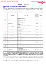
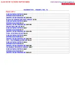
DIAGNOSTIC TROUBLE CODE CHART
HINT:
Parameters listed in the chart may not be exactly the same as your reading due to the type of instrument
or other factors. If a malfunction code is displayed during the DTC check in test mode, check the circuit for
that code listed in the table below. For details of each code, turn to the page referred to under the ”See page
” for the respective ”DTC No.” in the DTC chart.
DTC No.
( S ee P age)
Detection Item
Trouble Area
*1
Check Engine
Warning Light
Normal Mode/
Test Node
*2 Memory
12
NE Signal Circuit
S
Open or short in NE circuit
S
IIA
S
Open or short in STA circuit
S
Engine ECU
ON / N.A.
f
13
NE Signal Circuit
S
Open or short in NE circuit
S
IIA
S
Engine ECU
ON / ON.
f
14
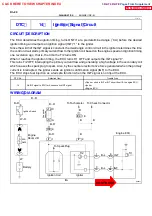
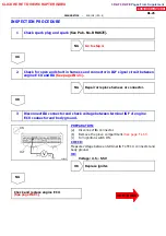
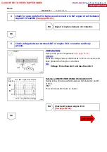
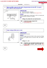
Ignition Signal Circuit
S
Open or short in IGF or IGT circuit from IIA to engine ECU
S
Igniter
S
Engine ECU
ON / N.A.
f
22
Water Temp. Sensor Circuit
S
Open or short in water temp. sensor circuit
S
Water temp. sensor
S
Engine ECU
ON / ON
f
24
Intake Air Temp. Sensor
Circuit
S
Open or short intake air temp. sensor circuit
S
Intake air temp. sensor
S
Engine ECU
OFF / ON
f
31
Vacuum Sensor Circuit
S
Open or short in vacuum sensor circuit
S
Vacuum sensor
S
Engine ECU
ON / ON
f
41
Throttle Position Sensor Circuit
S
Open or short in throttle position sensor circuit
S
Throttle position sensor
S
Engine ECU
OFF / ON
f
42
Vehicle Speed Sensor Signal
Circuit
S
Open or short in vehicle speed sensor circuit
S
Vehicle speed sensor
S
Combination meter
S
Engine ECU
ON / OFF
f
43
Starter Signal Circuit
S
Open or short in starter signal circuit
S
Open or short in ignition switch or starter relay circuit
S
Engine ECU
N.A. / OFF
X
51
Switch Condition
Circuit
S
A/C switch system
S
Throttle position sensor IDL circuit
S
Accelerator pedal and cable
S
Engine ECU
N.A. / OFF
X
*1: ”ON” displayed in the diagnosis mode column indicates that the check engine warning light is lighted
up when a malfunction is detected. ”OFF” indicates that the ”CHECK ENGINE” does not light up during mal-
function diagnosis, even if a malfunction is detected. ”N.A.” indicates that the item is not included in malfunc-
tion diagnosis.
*2: ”
f
” in the memory column indicates that a diagnostic trouble code is recorded in the ECU memory when
a malfunction occurs. ”X” indicates that a diagnostic trouble code is not recorded in the ECU memory even
if a malfunction occurs.
Accordingly, output of diagnostic results in normal or test mode is done with the IG switch ON.
CLICK HERE TO VIEW CHAPTER INDEX
Pages From Supplement
3RZ-F,3RZ-FE

