A00505
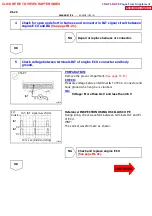
NE
2 V/
20m sec./Division(Idling)
NE Signal Waveforms
Division
(Idling)
A02470
NE Signal Sensor
Engine ECU
E4
E4
21
9
E1
NE--
4
2
G
R
NE+
16
16
DI--20
--
DIAGNOSTICS
ENGINE (1RZ--E)
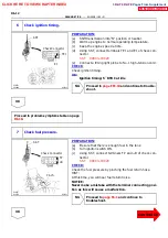
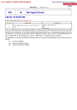
DTC 12 NE Signal Circuit
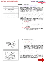
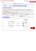
CIRCUIT DESCRIPTION
The IIA in the Engine Control System contains signal plate and a pickup coil for NE signal.
The NE signal plate has 4 teeth on its outer circumference. The NE signal sensor generates 4 signals for
every engine revolution. The ECU detects the engine speed by the NE signals.
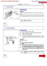
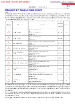
DTC No.
Detection Item
Trouble Area
12
No NE signal to ECU during cranking
S
Open or short in NE circuit
S
IIA
S
Open or short in STA circuit
S
Engine ECU
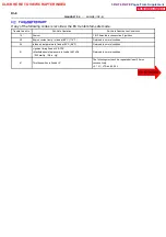
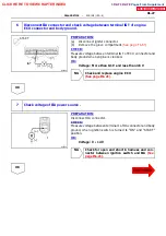
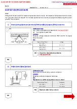
Reference: INSPECTION USING OSILLOSCOPE
During cranking or idling, check between terminals NE+ and
NE-- of engine ECU.
HINT:
The correct wavaforms are as shown.
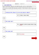
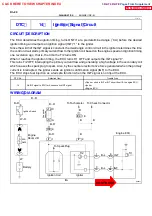
WIRING DIAGRAM
DI1HN--01
CLICK HERE TO VIEW CHAPTER INDEX
Pages From Supplement
3RZ-F,3RZ-FE

