5-4
Troubleshooting Visual Alarm Codes
Overview
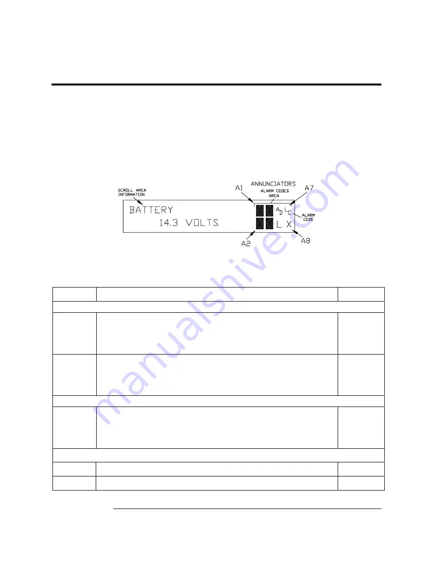
When a visual indicator is present (see
Figure 5–2
) the following section will assist in
determining the probable cause and steps required to correct the condition.
For the purpose of troubleshooting, only those codes considered to be alarms or codes
used to assist troubleshooting are discussed here. The entire list of Status and Alarm codes
may be found in Chapter 1, Table 1–3. Table 5–1 contains a description of each
XRC alarm
code. An alarm can be a word, character, letter or symbol.
An application can be assigned to an Annunciator and any alarms or status codes
associated with that application will be displayed.
Figure 5–2 Liquid Crystal Display and Indicators
Table 5–1 Visual Alarm Codes
Indicator Description Alarm
I/O Sub-System
L
L
Low Lithium Battery Alarm
: When
L
L
(low lithium) is displayed,
lithium battery voltage is below 2.5 Vdc. If battery voltage is
above 2.5VDC, A1 appears shaded. A new lithium battery
measures approximately 3.6 Vdc.
Y
L
C
Low Charger.
Displayed if
XRC battery charging voltage is less
than (+)0.4 Vdc higher than battery voltage. If charging voltage is
(+)0.4 Vdc greater than battery voltage then annunciator is
shaded.
Y
Measurement Application
A
D
A to D Failure.
Displayed if A to D Converter Absolute Differential
Pressure, Absolute Static Pressure or temperature readings
exceed maximum counts or are less than minimum counts. If A to
D Converter readings are within range, AD is shaded.
Y
Communication Protocols
→
Transmitting Data: Sending a response
N
←
Receiving Data: Processing request.
N
Continued on Next Page
Содержание XRC6490
Страница 1: ...2100802 001 AB TOTALFLOW XSeries Remote Controller User s Manual ...
Страница 6: ...iv B B Bl lla a an n nk k k P P Pa a ag g ge e e ...
Страница 10: ...viii B B Bl lla a an n nk k k P P Pa a ag g ge e e ...
Страница 19: ...1 5 Standard Enclosure Cont RC 6790 X Figure 1 2 Model XRC6790 Continued on Next Page ...
Страница 20: ...1 6 Standard Enclosure Cont 18 00 15 52 RC 6890 X 28 81 15 52 28 00 20 09 18 70 Figure 1 3 Model XRC6890 ...
Страница 24: ...1 10 XRC 195 Board Specifications Cont Figure 1 5 Complete View XRC 195 Board Continued on Next Page ...
Страница 41: ...1 27 Totalflow Input Output Modules Cont Figure 1 16 XRC6990 Inside View ...
Страница 42: ...1 28 B B Bl lla a an n nk k k P P Pa a ag g ge e e ...
Страница 56: ...2 14 AC Charging Unit Installation Cont Figure 2 12 DC Wiring Instructions Figure 2 13 AC Wiring Instructions ...
Страница 63: ...2 21 XRC Communication Jumper Settings and Field Wiring Cont Figure 2 19 Other Field Wiring I O Connections ...
Страница 64: ...2 22 B B Bl lla a an n nk k k P P Pa a ag g ge e e ...
Страница 86: ...4 12 Replacing XRC 195 Board Cont Figure 4 5 XRC Board Connections ...
Страница 88: ...4 14 B B Bl lla a an n nk k k P P Pa a ag g ge e e ...
Страница 112: ...5 24 12V Communication Supply Voltage Test Cont Figure 5 9 XRC 195 Communication Wiring ...
Страница 292: ...A 176 B B Bl lla a an n nk k k P P Pa a ag g ge e e ...
Страница 340: ...B 48 B B Bl lla a an n nk k k P P Pa a ag g ge e e ...
Страница 342: ...C 2 B B Bl lla a an n nk k k P P Pa a ag g ge e e ...


