


89
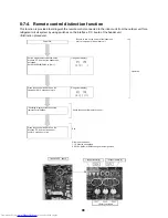
8-7. Service support function
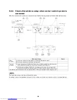
8-7-1. Check function for connecting of refrigerant and control
lines
This function is provided to check misconnection of the refrigerant pipes and the control transmission line (Wiring
over lines) between indoor unit and outdoor unit by using the switch on the interface P.C. board of the header unit.
However, be sure to check the following items prior to executing this check function.
1
This check function does not work when a group operation by remote control is performed and it
is used over outdoor units.
2
When using this check system, be sure to check for each 1 line in the unit of outdoor unit. If
checking the multiple lines at the same time, misjudgment may be caused.
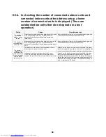
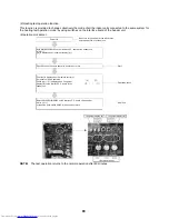
(Check procedure)
Power ON
Be sure to turn on the power at indoor
side before power-ON of outdoor unit.
System capacity check
Set the rotary switches SW01/SW02/SW03 on the interface
P.C. board of the header unit to [1/2/3]. Then the system
capacity is displayed on 7-segment display [A]. Check that
this display surely matches with the expected system
capacity.
Check No. of outdoor units
Set the rotary switches SW01/SW02/SW03 on the interface
P.C. board of the header unit to [1/3/3]. Then No. of outdoor
units connected to the system is displayed on 7-segment
display [A]. Check that this display surely matches with the
expected No. of outdoor units.
Check No. of indoor units/No. of units with cooling thermo
ON
Set the rotary switches SW01/SW02/SW03 on the interface
P.C. board of the header unit to [1/4/3]. Then No. of indoor
units connected to the system is displayed on 7-segment
display [A]. Check that this display surely matches with the
expected No. of indoor units.
Check No. of indoor units/No. of units with heating thermo
ON
Set the rotary switches SW01/SW02/SW03 on the interface
P.C. board of the header unit to [1/5/3]. Then No. of indoor
units connected to the system is displayed on 7-segment
display [A]. Check that this display surely matches with the
expected No. of indoor units.
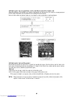
Check incorrect wiring
According to the indoor temperature, select one of the
following items for setup of the rotary switches on the
interface P.C. board of the header unit.
Cooling: SW01/SW02/SW03 to [2/1/1]
Heating: SW01/SW02/SW03 to [2/2/1]
(7-segment display)
System horsepower
(7-segment display)
No. of
connected
outdoor units
No. of
connected
outdoor
units
No. of units
with cooling
thermo ON
No. of
connected
outdoor
units
No. of units
with cooling
thermo ON
(7-segment display)
(7-segment display)
(7-segment display)
Cooling
Heating
Ind
oor t
e
mpera
tu
re [°
F
(°C)]
Outdoor temperature [°F(°C)]
SW02 to
[2]
(Heating)
SW02 to
[1]
(Cooling)
Содержание MMY-MAP0724HT6UL
Страница 229: ...228 15Exploded Diagram Parts Price List SMMS i OUTDOOR UNIT MMY MAP0724HT6UL ...
Страница 230: ...229 MMY MAP0724HT6UL ...
Страница 232: ...231 SMMS i OUTDOOR UNIT MMY MAP0964HT6UL MMY MAP1144HT6UL ...
Страница 233: ...232 MMY MAP0964HT6UL MMY MAP1144HT6UL ...
Страница 237: ...236 SMMS i INV SERVICE PARTS LIST MMY MAP0724HT6UL 4 pieces PC board ...
Страница 238: ...237 SMMS i INV SERVICE PARTS LIST MMY MAP0964HT6UL MMY MAP1144HT6UL 4 pieces PC board ...
Страница 241: ...Copyright 2011 TOSHIBA CARRIER CORPORATION ALL Rights Reserved ...


