


108
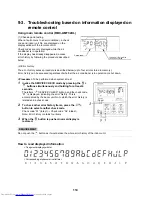
9-2. Troubleshooting method
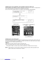
The remote controls (main remote control and central control remote control) and the interface P.C. board of an
outdoor unit are provided with an LCD display (remote control) or a 7-segment display (outdoor interface P.C.
board) to display operational status. Using this self-diagnosis feature, the fault site/faulty part may be identified in
the event of a fault by following the method described below.
The list below summarizes check codes detected by various devices. Analyze the check code according to where it is displayed and work out
the nature of the fault in consultation with the list.
• When investigating a fault on the basis of a display provided on the indoor remote control or TCC-LINK central control remote control - See
the “TCC-LINK remote control or main remote control display” section of the list.
• When investigating a fault on the basis of a display provided on an outdoor unit - See the “Outdoor 7-segment display” section of the list.
• When investigating a fault on the basis of a wireless remote control-controlled indoor unit - See the “Light sensor indicator light block” section
of the list.
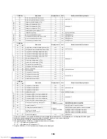
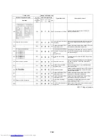
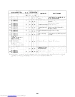
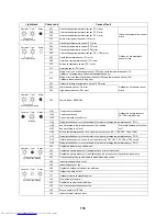
List of Check Codes (Indoor Unit)
(Error detected by indoor unit)
Check code
Display of receiving unit
Typical fault site
Description of error
TCC-LINK central
control or main
remote control
display
Outdoor 7-segment display
Indicator light block
Sub-code
Flash
E03
–
–
Indoor-remote control periodic
communication error
Communication from remote control or network
adaptor has been lost (so has central control
communication).
E04
–
–
Indoor-outdoor periodic
communication error
Signals are not being received from outdoor unit.
E08
E08 Duplicated indoor address
Duplicated indoor address
Indoor unit detects address identical to its own.
E10
–
–
Indoor inter-MCU communication
error
MCU communication between main controller and
motor microcontroller is faulty.
E18
–
–
Error in periodic communication
between indoor header and follower
unit
Periodic communication between indoor header
and follower units cannot be maintained.
F01
–
–
ALT Indoor heat exchanger temperature
sensor (TCJ) error
Heat exchanger temperature sensor (TCJ) has
been open/short-circuited.
F02
–
–
ALT Indoor heat exchanger temperature
sensor (TC2) error
Heat exchanger temperature sensor (TC2) has
been open/short-circuited.
F03
–
–
ALT Indoor heat exchanger temperature
sensor (TC1) error
Heat exchanger temperature sensor (TC1) has
been open/short-circuited.
F10
–
–
ALT Ambient temperature sensor (TA)
error
Ambient temperature sensor (TA) has been open/
short-circuited.
F11
–
–
ALT Discharge temperature sensor (TF)
error
Discharge temperature sensor (TF) has been
open/short-circuited.
F29
–
–
SIM P.C. board or other indoor error
Indoor EEPROM is abnormal (some other error
may be detected).
L03
–
–
SIM Duplicated indoor group header unit There is more than one header unit in group.
L07
–
–
SIM Connection of group control cable
to stand-alone indoor unit
There is at least one stand-alone indoor unit to
which group control cable is connected.
L08
L08
–
SIM Indoor group address not set
Address setting has not been performed for one or
more indoor units (also detected at outdoor unit
end).
L09
–
–
SIM Indoor capacity not set
Capacity setting has not been performed for indoor
unit.
L20
–
–
SIM Duplicated central control address There is duplication in central control address
setting.
L30
L30 Detected indoor unit No.
SIM Indoor external error input
(interlock)
Unit shutdown has been caused by external error
input (CN80).
P01
–
–
ALT Indoor AC fan error
Indoor AC fan error is detected (activation of fan
motor thermal relay).
P10
P10 Detected indoor unit No.
ALT Indoor overflow error
Float switch has been activated.
P12
–
–
ALT Indoor DC fan error
Indoor DC fan error (e.g. overcurrent or lock-up) is
detected.
P31
–
–
ALT Other indoor unit error
Follower unit cannot be operated due to header
unit alarm (E03/L03/L07/L08).
IPDU: Intelligent Power Drive Unit (Inverter P.C. board)
: Lighting,
: Flashing,
: Goes off
ALT.: Flashing is alternately when there are two flashing LED
SIM: Simultaneous flashing when there are two flashing LED
Operation Timer
Ready
Содержание MMY-MAP0724HT6UL
Страница 229: ...228 15Exploded Diagram Parts Price List SMMS i OUTDOOR UNIT MMY MAP0724HT6UL ...
Страница 230: ...229 MMY MAP0724HT6UL ...
Страница 232: ...231 SMMS i OUTDOOR UNIT MMY MAP0964HT6UL MMY MAP1144HT6UL ...
Страница 233: ...232 MMY MAP0964HT6UL MMY MAP1144HT6UL ...
Страница 237: ...236 SMMS i INV SERVICE PARTS LIST MMY MAP0724HT6UL 4 pieces PC board ...
Страница 238: ...237 SMMS i INV SERVICE PARTS LIST MMY MAP0964HT6UL MMY MAP1144HT6UL 4 pieces PC board ...
Страница 241: ...Copyright 2011 TOSHIBA CARRIER CORPORATION ALL Rights Reserved ...


