


81
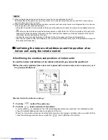
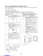
8-5-2. Operation from the indoor remote control is not accepted,
and a check code is displayed on the 7-segment display of
the interface PC board of the header unit.
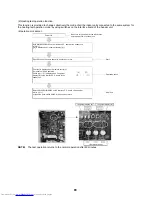
8-5-3. There is no display of a check code on the 7-segment
display on the interface PC board of the header unit,
although there is indoor unit that is not accepting operation
from the indoor remote control.
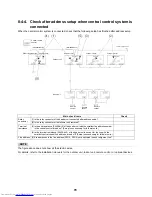
Indoor remote
control status
Header unit
7-segment
display
Cause
Countermeasures
No response
L08
Line addresses and indoor addresses of all the connected
indoor units are not set.
Set up addresses.
There is no header unit of group control.
Set up a group address.
E19
⇔
-00
Alternate
blinking
Indoor unit power is not turned on.
Turn on the power again. (In the order:
indoor
➝
outdoor)
Indoor/outdoor communication line is not correctly connected
to the U1/U2 terminal of the header unit ( Fig. 1). (Indoor/
outdoor cannot communicate before address setup.)
Correct wiring
There is no of outdoor terminal resistance, or there
are two or more resistances (before address setup).
Check SW30 bit 2 of the header unit.
No connection between multiple refrigerant
lines: SW30 bit 2 is on.
Connection between multiple refrigerant
lines: SW30 bit 2 of the connected header
unit is turned on only for one line.
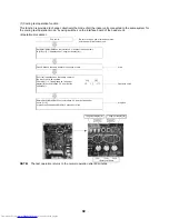
E19
⇔
-02
Alternate
blinking
When connecting an indoor/outdoor communication line
between outdoor units under the condition of a connected
communication line between outdoor units ( Fig. 2).
Correct wiring
SW08 setup error
Turn all SW08 switches to “off.”
E20
⇔
-01
Alternate
blinking
Address setup is performed with connecting an indoor/
outdoor communication line between outdoor units ( Fig. 3).
Correct wiring
Address setup is performed under the condition of
connecting multiple refrigerant lines ( Fig. 3).
Correct wiring
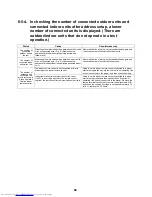
Indoor remote
control status
Header unit
7-segment
display
Cause
Countermeasures
No response
None
The communication line is not connected between indoor
and outdoor (the unit that does not respond to the indoor
remote control).
Modify the wiring.
Line address and indoor address are not set (the unit that
does not respond to the indoor remote control).
Set up the address.
The power of the header unit of the group is not turned on in
indoor group control (the unit that does not respond to the
indoor remote control).
Turn on the power.
Group address is set to the follower unit for individual control
(the unit that does not respond to the indoor remote control).
Set the group address to “0” in the case of
individual control.
No display on the
indoor remote
control (no line is
output.)
None
The power is not turned on (the unit that is not displayed on
the indoor remote control).
Turn on the power.
The indoor remote control is not connected with a wire (the
unit that is not displayed on the indoor remote control).
Modify the wiring.
Miswiring of the indoor remote control (the unit that is not
displayed on the indoor remote control)
Modify the wiring.
Indoor remote control communication circuit error (the unit
that is not displayed on the indoor remote control)
If 460 V is incorrectly applied to the indoor remote control
terminal, the remote control communication circuit fails.
Remove the fast-on terminal connected to
indoor remote control terminals A/B, and
check the voltage. If voltage is not applied
(normally 15 to 18 V), replace the PC board.
Содержание MMY-MAP0724HT6UL
Страница 229: ...228 15Exploded Diagram Parts Price List SMMS i OUTDOOR UNIT MMY MAP0724HT6UL ...
Страница 230: ...229 MMY MAP0724HT6UL ...
Страница 232: ...231 SMMS i OUTDOOR UNIT MMY MAP0964HT6UL MMY MAP1144HT6UL ...
Страница 233: ...232 MMY MAP0964HT6UL MMY MAP1144HT6UL ...
Страница 237: ...236 SMMS i INV SERVICE PARTS LIST MMY MAP0724HT6UL 4 pieces PC board ...
Страница 238: ...237 SMMS i INV SERVICE PARTS LIST MMY MAP0964HT6UL MMY MAP1144HT6UL 4 pieces PC board ...
Страница 241: ...Copyright 2011 TOSHIBA CARRIER CORPORATION ALL Rights Reserved ...


