December 2000 © TOSHIBA TEC
2 - 21
DP4500/3500 ADJUSTMENT
2.5 High-Voltage Adjustment
(1) Preparation
Developer unit
Cleaner unit
Developer unit
connector of the copier
(+) terminal
(–) terminal
Function switch
Full-scale
Remarks
How to turn on the power
Remarks
Developer Bias
Main Charger
Transfer Charger
Separation Charger
Disconnect the connector.
Remove the drum and
install the cleaner unit in
the copier.
Not connected
Connect in the hole at the
front side of the developer
unit.
Connect to the machine
frame (to ground).
Connect to the main
charger case (between the
case and the terminal).
Connect with the red cable of the current
measuring jig.
DC
AC
1,000 V
2V
Use a digital tester with an input resistance of 10 M (RMS value) or higher.
Refer to (b) Connection
Refer to (c) Connection Refer to (d) Connection for
for developer bias
for main charger
transfer/separation charger adjustment.
adjustment.
adjustment.
Attach the door switch jig and press the front cover opening/closing switch while the front cover is open.
Remove from the copier. (Not used)
Install the unit together with the current measuring jig in the copier.
NOTE 1:Connect the green cable of the current measuring jig to ground on the
copier frame. Refer to (a) Installation of current measuring jig.
Connect the jig detection conector with the developer unit connector of the
copier.
Digital T
ester
Connect with the white cable of the current measuring jig (to ground).
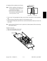
(a) Installation of the current measuring jig
Notes: 1. Clean the toner recovery auger when the
toner is sticking to it. Then attach the jig.
2. Do not damage the tip of the separation
fingers.
3. Remove the cleaner stay before installing
the jig.
1. Unlock the cleaning blade using the blade
releasing jig. (
Chapter 11.5 [C] in the Serv-
ice Manual)
2. Insert the shaft through the hole at the front side of the cleaner.
3. Put the shaft through the current measuring jig and put it into the rear hole to fix it to the cleaner. Attach
the cleaner stay.
4. Install the cleaner unit in the copier with 2 screws, and connect the jig detection connector with the
connector of the developer unit in the copier.
Fix the green cable of the current measuring jig to the machine frame.
Notes: 1. Set the current measuring jig in the center of the cleaner unit.
2. High-voltage adjustment cannot be performed without connecting the jig detection connector
(except the developer bias adjustment).
Содержание DP3500
Страница 91: ...DP4500 3500 PREVENTIVE MAINTENANCE 3 12 December 2000 TOSHIBA TEC ...
Страница 95: ...DP4500 3500 SUPPLIES 4 4 December 2000 TOSHIBA TEC ...
Страница 213: ...DP4500 3500 TROUBLESHOOTING 5 118 December 2000 TOSHIBA TEC ...
Страница 253: ...DP4500 3500 UPDATING THE FIRMWARE 6 40 December 2000 TOSHIBA TEC ...
Страница 254: ...December 2000 TOSHIBA TEC 7 1 DP4500 3500 WIRE HARNESS CONNECTION DIAGRAMS 7 WIRE HARNESS CONNECTION DIAGRAMS ...
Страница 256: ...DP4500 3500 WIRE HARNESS CONNECTION DIAGRAMS 7 4 December 2000 TOSHIBA TEC ...


