December 2000 © TOSHIBA TEC
1 - 17
DP4500/3500 ERROR CODES AND SELF-DIAGNOSIS
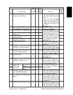
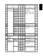
Adjustment mode (05)
Accept-
Operation
Code
Items to adjust
Mode Default
able
Contents
procedure
value
group
200
201
205
210
221
231
286
305
306
308
340
354
355
356
357
358
Automatic adjustment of auto-toner
sensor (Fuser heater ON)
Manual adjustment of auto-toner sen-
sor initial value(Fuser heater ON)
Developer bias DC output adjustment
Main charger grid bias output
adjustment
Transfer transformer DC output adjust-
ment/center value
Separation transformer AC output
adjustment/center value
Laser power adjustment
Adjustment of scanner secondary
scanning start position deviation
Adjustment of scanner primary scan-
ning start position deviation
Distortion mode
Adjustment of scanner secondary
scanning reproduction ratio
Adjustment of
for single-sided
RADF paper
paper
alignment
for double-sided
paper
Automatic adjustment of RADF sen-
sor and EEPROM initialization
Fine adjustment of RADF transport
speed
RADF sideways deviation adjustment
ALL
–
–
ALL
128
0~255
ALL
193
0~255
ALL
158
0~255
ALL
117
0~255
ALL
159
0~255
ALL
117
0~255
ALL
128
0~255
ALL
128
0~255
ALL
–
–
ALL
128
0~255
ALL
10
0~20
ALL
10
0~20
ALL
–
–
ALL
50
0~100
ALL
128
0~255
- As the value increases, the sen-
sor output increases correspond-
ingly.
- The value starts changing
approx. 2 minutes after this ad-
justment was started and is auto-
matically set in the range of 2.35
to 2.45V.
(
chapter 2.2)
Adjustment value of auto-toner
sensor can be displayed.
As the value increases by “1”, out-
put from the transformer increases
correspondingly. Remove the de-
veloper unit and install the service
jig to make adjustment. However,
the service jig is not necessary to
adjust the developer bias DC.
(
chapter 2.5)
When the value increases by “1”,
the laser output increases corre-
spondingly.
When the value increases by “1”,
the image shifts toward the leading
edge of paper by approx. 0.17mm.
When the value increases by “1”,
image shifts toward the rear side
of paper by approx. 0.0423mm.
Moves the carriages to the adjust-
ment position.
(
chapter 2.3.4)
When the value increases by “1”,
the reproduction ratio of the sec-
ondary scanning direction de-
creases by approx. 0.025%.
When the value increases by “1”,
the aligning amount increases by
approx. 0.5mm.
Perform the adjustment and initiali-
zation when the PC board or sen-
sor of the RADF is replaced.
When the value increases by “1”,
the reproduction ratio of the sec-
ondary scanning direction on origi-
nal fed from the RADF increases
by approx. 0.1%.
When the value increases by “1”,
the image of original fed from the
RADF shifts toward the rear side
of paper by approx. 0.0423mm.
–
2
2
2
2
2
2
1
1
4
1
1
1
4
1
1
Содержание DP3500
Страница 91: ...DP4500 3500 PREVENTIVE MAINTENANCE 3 12 December 2000 TOSHIBA TEC ...
Страница 95: ...DP4500 3500 SUPPLIES 4 4 December 2000 TOSHIBA TEC ...
Страница 213: ...DP4500 3500 TROUBLESHOOTING 5 118 December 2000 TOSHIBA TEC ...
Страница 253: ...DP4500 3500 UPDATING THE FIRMWARE 6 40 December 2000 TOSHIBA TEC ...
Страница 254: ...December 2000 TOSHIBA TEC 7 1 DP4500 3500 WIRE HARNESS CONNECTION DIAGRAMS 7 WIRE HARNESS CONNECTION DIAGRAMS ...
Страница 256: ...DP4500 3500 WIRE HARNESS CONNECTION DIAGRAMS 7 4 December 2000 TOSHIBA TEC ...


