


S
SLA/W
A
DATA
A
P or S
Reception of own
address and data
bytes. All are
acknowledged.
UCRXIFG=1
DATA
DATA
A
A
UCTXNACK=1
Refer to:
”Slave Transmitter”
Timing Diagram
Bus not stalled even if
UCBxRXBUF not read
P or S
DATA
A
A
Arbitration lost as
master and
addressed as slave
UCALIFG=1
UCMST=0
UCTR=0 (Receiver)
UCSTTIFG=1
(UCGC=1 if general call)
Last byte is not
acknowledged.
UCTR=0 (Receiver)
UCSTTIFG=1
UCSTPIFG = 0
Gen Call
A
UCTR=0 (Receiver)
UCSTTIFG=1
UCGC=1
Reception of the
general call
address.
UCTXNACK=0
Bus stalled
(SCL held low)
if UCBxRXBUF not read
Read data from UCBxRXBUF
UCSTPIFG=0
UCTXIFG=0
UCSTPIFG=0
eUSCI_B Operation – I
2
C Mode
If the master generates a repeated START condition, the eUSCI_B I
2
C state machine returns to its
address-reception state.
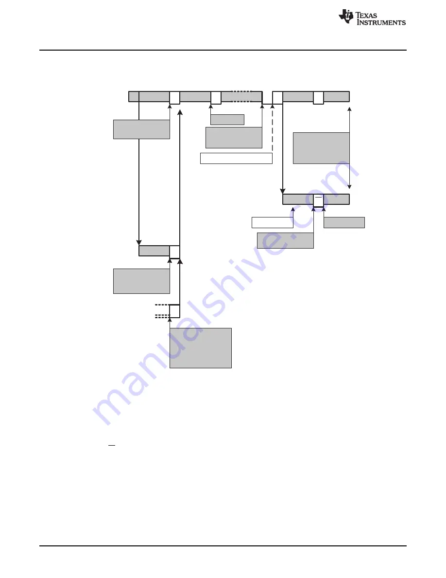
shows the I
2
C slave receiver operation.
Figure 20-10. I
2
C Slave Receiver Mode
20.3.5.1.3 I
2
C Slave 10-Bit Addressing Mode
The 10-bit addressing mode is selected when UCA10 = 1 and is as shown in
. In 10-bit
addressing mode, the slave is in receive mode after the full address is received. The eUSCI_B module
indicates this by setting the UCSTTIFG flag while the UCTR bit is cleared. To switch the slave into
transmitter mode, the master sends a repeated START condition together with the first byte of the address
but with the R/W bit set. This sets the UCSTTIFG flag if it was previously cleared by software, and the
eUSCI_B modules switches to transmitter mode with UCTR = 1.
540
SLAU272C – May 2011 – Revised November 2013
Enhanced Universal Serial Communication Interface (eUSCI) – I
2
C Mode
Copyright © 2011–2013, Texas Instruments Incorporated