


Second
Capture
Taken
COV = 1
Capture
aken
T
No
T
Capture
aken
Read
Taken
Capture
Clear Bit COV
in Register TBxCCTLn
Idle
Idle
Capture
Capture Read and No Capture
Capture
Capture Read
Capture
n–2
n 1
–
Timer Clock
Timer
n+1
n+3
n+4
CCI
Capture
n+2
n
Timer_B Operation
The capture signal can be asynchronous to the timer clock and cause a race condition. Setting the SCS
bit synchronizes the capture with the next timer clock. Setting the SCS bit to synchronize the capture
signal with the timer clock is recommended (see
).
Figure 12-10. Capture Signal (SCS = 1)
NOTE:
Changing Capture Inputs
Changing capture inputs while in capture mode may cause unintended capture events. To
avoid this scenario, capture inputs should only be changed when capture mode is disabled
(CM = {0} or CAP = 0).
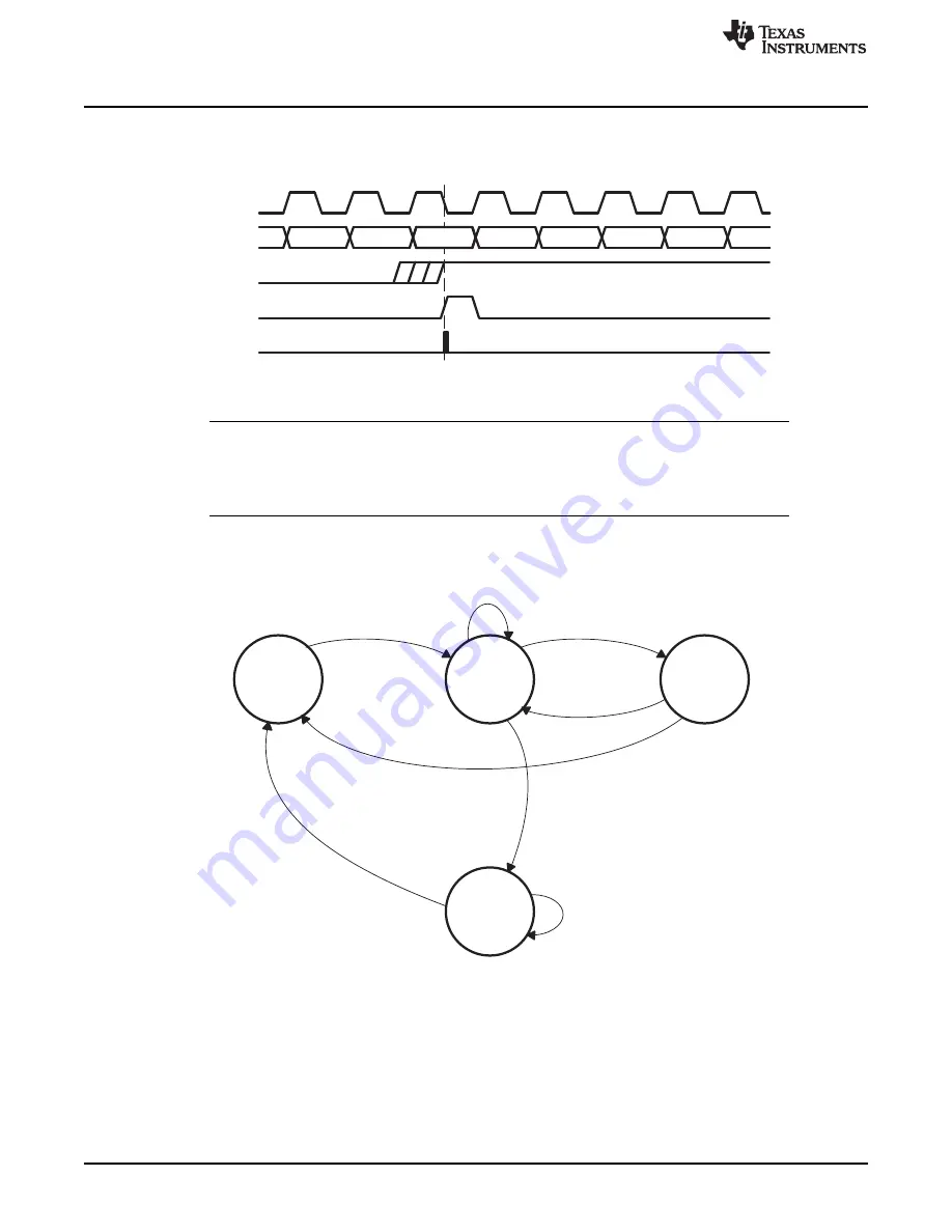
Overflow logic is provided in each capture/compare register to indicate if a second capture was performed
before the value from the first capture was read. Bit COV is set when this occurs (see
). COV
must be reset with software.
Figure 12-11. Capture Cycle
364
Timer_B
SLAU272C – May 2011 – Revised November 2013
Copyright © 2011–2013, Texas Instruments Incorporated