


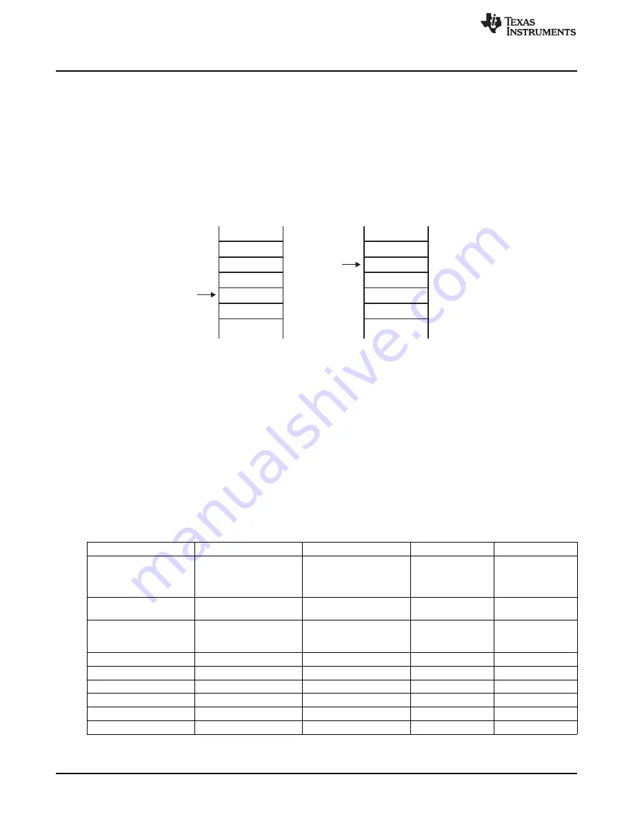
Item1
Item2
SP
TOS
Item1
Item2
SP
TOS
PC
SR
Before
After
PC
SR
Return From Interrupt
Interrupts
1.3.4.2
Return From Interrupt
The interrupt handling routine terminates with the instruction:
RETI //return from an interrupt service routine
The return from the interrupt takes five cycles to execute the following actions and is illustrated in
1. The SR with all previous settings pops from the stack. All previous settings of GIE, CPUOFF, and so
on are now in effect, regardless of the settings used during the interrupt service routine.
2. The PC pops from the stack and begins execution where it was interrupted.
Figure 1-4. Return From Interrupt
1.3.5 Interrupt Nesting
Interrupt nesting is enabled if the GIE bit is set inside an interrupt service routine. When interrupt nesting
is enabled, any interrupt occurring during an interrupt service routine interrupts the routine, regardless of
the interrupt priorities.
1.3.6 Interrupt Vectors
The interrupt vectors are located in the address range 0FFFFh to 0FF80h, for a maximum of 64 interrupt
sources. A vector is programmed by the user and points to the start location of the corresponding interrupt
service routine.
is an example of the interrupt vectors available. See the device-specific data
sheet for the complete interrupt vector list.
Table 1-1. Interrupt Sources, Flags, and Vectors
Interrupt Source
Interrupt Flag
System Interrupt
Word Address
Priority
Reset:
...
...
...
...
power up, external reset
WDTIFG
Reset
0FFFEh
Highest
watchdog,
FRCTLPW
FRAM password
System NMI:
JMBINIFG, JMBOUTIFG
(Non)maskable
0FFFCh
…
JTAG Mailbox
User NMI:
...
...
...
...
NMI
NMIIFG
(Non)maskable
0FFFAh
…
oscillator fault
OFIFG
(Non)maskable
Device specific
0FFF8h
…
...
...
...
Watchdog timer
WDTIFG
Maskable
...
...
...
...
...
Device specific
…
…
Reserved
Maskable
…
Lowest
32
System Resets, Interrupts, and Operating Modes, System Control Module (SYS)
SLAU272C – May 2011 – Revised November 2013
Copyright © 2011–2013, Texas Instruments Incorporated