Teledyne Sierra M6-2 Скачать руководство пользователя страница 33

Sierra M6

2 SAS/SATA Protocol Analyzer User Manual

31

Expandability

 Teledyne LeCroy

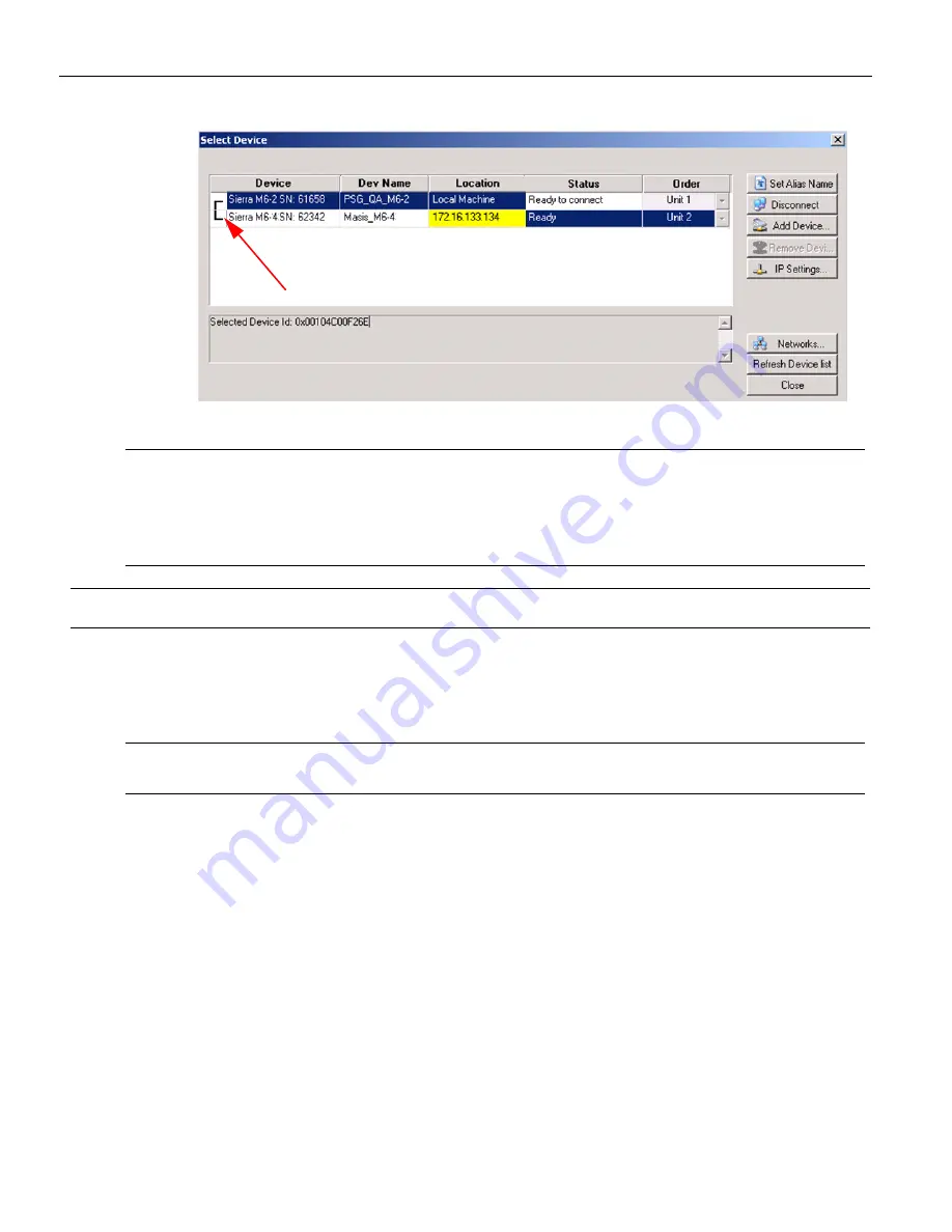
Figure 1.18: Select Device Dialog Displaying Unit 1 and Unit 2 Chained 

Note:

When using STX Sync cards, you need to manually specify the order of the chained units. To 

match your unit sequence to the address for each unit in the Select Device dialog, click the 
pull down tab under the Order heading (on the right side) and select unit numbers: 1 for 
Unit 1, 2 for Unit 2, and so on. This determines the order in which the cascaded ports appear in 
the trace. When using the CATC Sync cards the order is automatically detected. 

IMPORTANT!

Power up all units before starting the software. 

1.9.3

Cascading with CATC SYNC Expansion Card

You can cascade up to eight Sierra Analyzers, if they all have a CATC SYNC expansion card.

Note:

If Sierra M6

2 has a CATC SYNC Expansion Card, you can cascade with Sierra M6

1. If Sierra M6

has an STX SYNC Expansion Card, you cannot cascade with Sierra M6

1.

1.9.4

Using the Power Expansion Card

Two types of Power Expansion Cards are available and the type must be specified when 
ordering the unit. 

Power Expansion Card (part number: ACC

EXP

004

X)

Power Expansion Card 2 (part number: ACC

EXP

005

X)

Power Expansion Card 

(part


number:


ACC

EXP

004

X)

You can use the Power Expansion Card to power the drives to test for Emulation, 
SATA Compliance, and SAS Verification. The Power Expansion Card can supply 5 V or 12 V.

Содержание Sierra M6-2

Страница 1: ...Sierra M6 2 SAS SATA Protocol Analyzer User Manual For software version 5 80 Generated March 3 2015 10 54 ...

Страница 2: ...CTS INTHIS MANUAL ARE SUBJECT TOCHANGE WITHOUT NOTICE ALLINFORMATION EXAMPLES ANDRECOMMENDATIONS IN THIS MANUALARE BELIEVED TO BE ACCURATE BUT ARE REPRESENTED WITHOUT WARRANTY OF ANY KIND EXPRESS OR IMPLIED USERS ARE FULLY RESPONSIBLE FOR THEIR APPLICATIONOF ANYPRODUCTS THE SOFTWARE LICENSE AND LIMITED WARRANTY FOR THE ACCOMPANYINGPRODUCT ARE SET FORTH IN INFORMATIONTHAT SHIPPEDWITH THE PRODUCT AN...

Страница 3: ...up 21 1 8 1 Separate Systems 21 1 8 2 Connecting in General 21 1 8 3 Cables to Use 22 1 9 Expandability 23 1 9 1 Cascading with STX SYNC Expansion Cards 24 Cascading 24 1 9 2 Select Device 26 1 9 3 Cascading with CATC SYNC Expansion Card 31 1 9 4 Using the Power Expansion Card 31 Power Expansion Card part number ACC EXP 004 X 31 Power Expansion Card 2 part number ACC EXP 005 X 32 1 9 5 Removing Ex...

Страница 4: ...1 21 7 View 44 1 21 8 Window 46 1 21 9 Help 46 1 21 10 Toolbars 46 1 22 Port Status 47 1 23 InFusion 47 1 24 Trainer 47 Chapter 2 Protocol Analysis 49 2 1 Easy Mode Pre Defined Setups 49 2 2 Main Window 49 2 3 Project Tree 51 2 3 1 Capture Tab Fields 51 Exclude XXXX 51 2 4 SAS SATA Software Menus and Toolbars 52 2 4 1 SAS Main Toolbar 52 2 4 2 SATA Main Toolbar 53 2 5 Start Recording 53 2 5 1 Laun...

Страница 5: ...ining Patterns 69 Primitive 70 Data Pattern 70 2 6 9 Protocol Errors 71 Protocol Error Descriptions 72 2 6 10 STP Frame 73 Available FIS Types 73 2 6 11 Address Frame SAS only 73 2 6 12 SMP Frame SAS only 74 2 6 13 SSP Frame SAS only 75 2 6 14 FIS Type Frame Information Structure SATA only 75 Available FIS Types 76 2 6 15 STP Frame Pattern 76 Register Host to Device 77 Register Device to Host 77 S...

Страница 6: ...only 102 Sequential Trigger Mode 103 Timer 103 Defining Patterns 104 Triggering Order 104 Pre Trigger 105 2 6 17 Project Settings 105 2 6 18 Memory Settings 106 Trigger Position 106 Trace File Name 107 Auto Run 107 Memory Size 107 Partial Memory 107 Segmented Memory 107 Upload Manager 107 2 6 19 Analyzer Settings 108 Primitive Response Timeout 108 Disable Descrambling 108 Show XXXX value 109 Pack ...

Страница 7: ...Commands 127 Adding an ATA Command 127 Adding a User Defined ATA Command 129 Adding a SCSI Command SAS only 129 Adding a User Defined SCSI Command SAS only 130 Adding a TASK Command SAS only 131 Adding an SMP Command SAS only 132 Adding a Frame 133 Adding an Event 134 Power On 135 PHY Setting Dialog 136 Inserting Instructions 136 Phy Reset Sequence and Identification 141 Sample Host Emulator Progr...

Страница 8: ... 186 Writable Buffer Size Field 187 Error Injection Tab 187 2 12 2 Setting General Errors 189 Generate Periodic Error 189 Outgoing FIS Command Error or Outgoing FRAME Command Error 189 Identify Errors SAS only 193 2 12 3 Connection Management SAS only 194 Open Connection Definition 194 Close Connection Definition 195 2 12 4 SAS Commands Errors SAS only 196 Outgoing Frame Settings 198 2 12 5 ATA Co...

Страница 9: ... Command Go to Response 234 3 3 4 Changing the Default View 236 3 3 5 Spreadsheet View 236 Export As Text Excel 237 Change Format of Logical Block Address LBA 238 3 3 6 Column View 238 3 3 7 Text View 239 Identify Device Frame 240 241 3 3 8 Frame Inspector View 241 3 3 9 Waveform Display 242 Performance Reference Definitions 243 3 3 10 Statistical Report 244 Generating Statistical Read Write Repor...

Страница 10: ... Toolbar 259 Export as Microsoft Excel file 260 Save as Text file 260 Print Statistical Report 260 Print Preview 260 Report Display Settings 261 Link With Sample View 262 3 3 12 Formatting the Statistical Report View 262 Filtering Column Content 262 Sorting Column Content 264 Hiding Columns 264 3 3 13 Histogram View 265 Hide Frames 265 Hide Error Frames 265 Pending IO Graph 266 User Defined 266 Pr...

Страница 11: ...ultilevel Filtering in SAS 289 Filter descending packets from trace highlight bar 291 3 8 4 Selectable Filter Options for SAS 291 Command Data Pattern 292 Bus Condition 292 Incomplete Frames 292 ATA Command 292 Protocol Error 292 ATAPI SCSI Command 292 Filter Check Condition 292 Filter by Tag Number 294 Use Pair SAS Addresses 296 Training Sequence 296 3 8 5 Selectable Filter Options for SATA 296 B...

Страница 12: ... 11 2 Cursor Position Status Bar 317 3 12 Status Bar 317 3 12 1 Search Status 317 3 13 Using the Cursors and Bookmarks 317 3 13 1 Cursors 317 3 14 Display Configuration 318 3 14 1 Trace Viewer Configuration 318 3 15 Set Port Alias 322 Restore Factory Presets 323 3 16 SAS Address Alias SAS only 323 3 17 TxRx Vout Preemphasis 324 3 18 Preferences 326 3 18 1 General Tab 326 Paths 326 Template Files 3...

Страница 13: ...Help Topics 340 3 23 3 VSE Help Topics 340 3 23 4 Update License 340 3 23 5 Display License Information 341 3 23 6 Check for Updates 342 3 23 7 About 342 3 24 Setup Menu 342 3 24 1 Self Test 342 3 24 2 Clock Check 343 3 24 3 Memory Check 344 3 24 4 Serdes Check 345 3 24 5 Crosspoint Check 346 3 24 6 Main FPGA Check SATA only 347 3 24 7 Expansion Check 348 3 24 8 LED Buzzer Check 349 3 25 Find DUT ...

Страница 14: ...o Events 385 4 7 1 DWORD Matcher 387 4 7 2 Address Frame 388 4 7 3 SAS Data Pattern 388 4 7 4 SATA Data Pattern 388 4 7 5 Analyzer Trigger 389 4 7 6 Adding NOT Property to SAS and SATA Primitives 390 4 8 Scenario Actions 390 4 8 1 Available Resources 393 Using Counters in Events and Actions 394 Capturing a Data DWORD 395 Using Captured Data DWORDs 395 4 8 2 Generating an Internal Trigger 397 4 8 3...

Страница 15: ...er 5 Sierra Trainer Traffic Generation 435 5 1 Sierra Trainer Menus 436 5 1 1 File Menu 436 5 1 2 Setup Menu 436 5 1 3 Generate Menu 437 5 1 4 Search Menu 438 5 1 5 View Menu 439 5 1 6 Tools Menu 440 5 1 7 Window Menu 440 5 1 8 Help Menu 440 5 2 Sierra Trainer Main Toolbar 440 5 3 Setting Up for Generating Initiator Traffic 441 5 4 Setting Up for Generating Target Traffic 442 5 5 Creating a Traffi...

Страница 16: ... 11 Generating Traffic 456 5 11 1 Stop Traffic Generation 457 5 11 2 Resume Traffic Generation 457 5 12 Sierra Trainer Generation Language 457 5 12 1 File Structure 457 5 12 2 Language 458 Comments 458 Includes 458 5 12 3 Settings 458 5 12 4 Constants 458 5 12 5 Predefined Constants 458 5 12 6 Data Patterns 459 5 12 7 Primitives 459 5 12 8 Packets Frames 461 5 12 9 Generation Block 463 5 12 10 Def...

Страница 17: ... Generation Rules Pop Up Menus 502 5 15 2 Cell Pop up Menu 503 5 15 3 Action Pop up Menu 503 5 15 4 Event Pop up Menu 503 5 15 5 Events and Event Properties 504 Data Pattern Mask and Match 504 5 16 Setting Complex Wait For Conditions 505 5 16 1 Setting Conditions with the Generation Options Dialog 505 5 17 Find 506 5 17 1 Data Pattern Mask and Match 509 5 17 2 Find Next 509 5 17 3 Search Direction...

Страница 18: ... 519 6 4 Loop definition format 519 6 5 Scramble definition format 519 6 6 Role definition format 519 6 7 END_OF_FILE definition 519 6 8 Example Pattern Generator File 520 Appendix B China Restriction of Hazardous Substances Table 521 7 1 WAN Operation 522 Appendix C How to Contact Teledyne LeCroy 523 Index 525 ...

Страница 19: ...Serial Attached SCSI SAS data transfers as well as Serial ATA SATA data transfers through STP data transfers The SATA analyzer software performs serial bus analysis for Serial ATA SATA data transfers The Sierra M6 2 Analyzer helps Hardware Firmware Design and Application Engineers troubleshoot and diagnose SAS and SATA problems within their product The analyzer supports the following Capture trigg...

Страница 20: ...ts 1 2 Features 6 Gb s SAS SATA protocol analysis or error injection Native PHY for fast lock time Easy mode triggering Cascade up to 8 analyzers Sync with Teledyne LeCroy Sierra and STX family products CrossSync Control Panel Hardware filtering Automatic error detection Comprehensive decoding of SAS and SATA data traffic Logical and chronological traffic displays Statistical reporting Trace memor...

Страница 21: ...1 Trigger Error Link Speed and Frame OOB LEDs see next page Port 1 Initiator Host SATA connector Port 1 Target Device SATA connector Port 2 Initiator Host SATA connector Port 2 Target Device SATA connector Status and Configuration LCD Display External Trigger Input and Output USB port for host connectivity Gigabit Ethernet port for network connectivity Power In on back Expansion In Out data ports ...

Страница 22: ... F Non Operating 20 C to 80 C 4 F to 176 F The hardware should operate in the following humidity range 10 to 90 RH non condensing 1 7 Installing Your Analyzer 1 7 1 Software Installation The SAS and SATA software works on systems using the Windows XP Windows 7 x86 x64 Windows 8 x86 x64 Windows Server 2003 Windows Server 2008 and Windows Server 2012 R2 operating systems 64 bit Windows OS is recomme...

Страница 23: ... bus traffic and a second system to run the software to avoid characterization of traffic generated by the analyzer 1 8 2 Connecting in General Note You must install the software before connecting the analyzer to the host machine for the first time To set up the analyzer 1 Plug the power adapter into the unit and then plug the power adapter into a 100V 240V 50Hz 60Hz power outlet Turn on the Power...

Страница 24: ...otocol Analyzer User Manual Figure 1 4 Analyzer Connections 1 8 3 Cables to Use When using Sierra as a Host Emulator connect from Target to hard drives using a SATA cable When using Sierra as a Device Emulator connect from Initiator to HBAs using a SATA cable ...

Страница 25: ...ty Teledyne LeCroy Figure 1 5 Sierra M6 2 Connected as an Analyzer 1 9 Expandability You can expand by Cascading with STX SYNC Expansion Cards Cascading with CATC SYNC Expansion Cards Using the Power Expansion Card You can remove expansion cards with two simple tools ...

Страница 26: ... must provide external hubs for connecting the host machine to these units using USB or Ethernet You can cascade up to eight units Use the STX SYNC Expansion Cards to sequentially trigger the State Machine in Advanced mode If you mix Sierra M6 4 Sierra M6 2 and STX A6 4 analyzers emulators put Sierra boards first then STX Note Because chain connections for cascading boards cause delay of signals t...

Страница 27: ...ance Test and Update License functions only work on unit 1 when the analyzers are set up in cascading mode Figure 1 7 Cascading Figure 1 8 Cascading Correctly Correct way to connect The black color pin of the ribbon wire is connected the same way between 2 connectors Cascading works correctly in this case Black color pin of ribbon wire ...

Страница 28: ...on Figure 1 10 Address Digits IMPORTANT Power up all units before starting the software 1 9 2 Select Device After starting the software click on Configuration and select All Connected Devices see the following screen capture Incorrect way to connect The black color pin of the ribbon wire is connected in a different way between the 2 connectors Cascading works incorrectly in this case the boxes are...

Страница 29: ... the analyzer over Ethernet Thus the analyzer must be updated over USB before it can be used remotely over Ethernet This is applicable for any update from version 4 00 or earlier to any version from 4 10 or later The following Select Device dialog displays see Figure 1 12 on page 28 The colors in the Location column mean the following Red Firmware and or BusEngine components need to be updated to ...

Страница 30: ...g Note Click Refresh Device List to display all the devices on the network The Select Device dialog displays the following buttons Set Alias Name Click Set Alias Name to display the Set device alias name dialog as shown below Figure 1 13 Set Device Alias Name Dialog Disconnect Click Disconnect to disconnect a device ...

Страница 31: ...Ping function fails the button in the upper right corner but you re sure the address is correct and you still want to attempt the connection This setting is stored in the device Remove Device Click Remove Device to remove a previously added device IP Settings Click IP Setting to reset IP settings of a device The following IP Setting dialog displays Figure 1 15 IP Setting Dialog Networks Click Netw...

Страница 32: ...ee the following screen capture Figure 1 17 Connection Properties Dialog Specify one of the actions from the following Automatically connect to the device Ask if I want to connect to the device Take no action If Automatically connect to the device is selected the next time the application opens the device will be automatically connected In the Select Device dialog chained or cascaded units are dis...

Страница 33: ...ORTANT Power up all units before starting the software 1 9 3 Cascading with CATC SYNC Expansion Card You can cascade up to eight Sierra Analyzers if they all have a CATC SYNC expansion card Note If Sierra M6 2 has a CATC SYNC Expansion Card you can cascade with Sierra M6 1 If Sierra M6 2 has an STX SYNC Expansion Card you cannot cascade with Sierra M6 1 1 9 4 Using the Power Expansion Card Two typ...

Страница 34: ...Allows toggling the new Device Sleep DevSlp signal to put SATA devices into sleep see Adding an Event on page 134 and Figure 2 129 on page 135 Allows monitoring in the trace of the DevSlp signal as generated by the Trainer or Host Emulator as well as when generated directly from a Host using a dedi cated DevSlp cable Also see Device Sleep DevSlp on page 232 Allows CATC Sync functionality to enable...

Страница 35: ...hen the Device is con nected directly to the Host It is up to the user to supply a copy of the DevSlp sig nal coming from the Host to connect to the DevSlp wire of this cable as well as to connect the adequate ground wire of this cable 1 9 5 Removing Expansion Cards You can remove both expansion cards using two tools Standard flat blade 3 16 screwdriver Teledyne LeCroy Extraction Tool part number ...

Страница 36: ...he holes use a small nail file or similar device to remove paint from the prongs 3 Rotate the extraction tool to a horizontal position to lock the prongs into place and make a handle 4 Using the screwdriver loosen both retaining screws by rotating them counter clockwise approximately two full turns until feeling slight resistance Do not force the retaining screws after two turns Holes in the Expan...

Страница 37: ...Sierra M6 2 SAS SATA Protocol Analyzer User Manual 35 Expandability Teledyne LeCroy ...

Страница 38: ...n can have any of these configurations 1 Analyzer connected to a network using a hub or switch Gigabit Ethernet interface or similar device 2 Analyzer connected to the host machine machine running the application software using a hub or switch Gigabit Ethernet interface or similar device 3 Analyzer connected directly to the host machine using a SATA cable 1 11 Connecting to a Network When connecte...

Страница 39: ...ewall documentation to allow Teledyne LeCroy applications access to the network The following TCP and UDP ports must be open to connect over the Ethernet TCP Port 4000 to 4003 UDP Ports 4015 to 4017 1 14 Launching Your Analyzer To launch the software double click the SAS or SATA Icon in the Program Manager Window 1 15 Operating in Simulation Mode The SAS SATA applications operate in Simulation Mod...

Страница 40: ...ion on page 184 Protocol Analyzer Host Emulator SATA Generates bus traffic for capture It also has Easy Mode and Advanced Mode see Emulation on page 125 Device Emulator SATA Acts as device see Target and Device Emulation on page 184 The SAS SATA application now provides functionality for both protocols Either protocol can now be accessed via the File menu and choosing the protocol to work with Cli...

Страница 41: ...rent patterns for pre trigger and post trigger On the Trigger tab select the trigger type For Pattern select the pattern On the Settings tab select trigger position and memory use Change the Analyzer settings if necessary Change the port Speed if necessary Use Advanced Mode only after you become familiar with the hardware and software and have special needs 1 18 Protocol Analyzer Initiator Emulato...

Страница 42: ... Device Emulator To use the software as a target or device emulator first select File New SAS Target Emulator or SATA Device Emulator for a new project or File Open an existing Emulator file std Target Emulator file or sde Device Emulator file see Target and Device Emulation on page 184 You can also use Project Setup Last Target Emulator or Last Device Emulator In the Pages tab change settings for...

Страница 43: ...e Figure 1 22 on page 42 to perform the following actions TxRxVout Pre emphasis see TxRx Vout Preemphasis on page 324 User Defined Decoding see User Defined Decoding on page 339 External Trig Setting see External Trig Setting on page 336 Update Device see Update Device on page 337 All Connected Devices see Select Device on page 26 Find DUT see Find DUT on page 350 Power Source Control see Power So...

Страница 44: ...s the capture without saving Stop Capture Record Stops the hardware Start Target Emulator Starts the target emulator SAS Stop Target Emulator Stops the target emulator SAS Start Device Emulator Starts the device emulator SATA Stop Device Emulator Stops the device emulator SATA 1 21 4 Analysis The Analysis menu see Figure 1 23 on page 43 allows you to view captured data see the following screen cap...

Страница 45: ...nspector View Has lots of information that is available in Packet View but not Spreadsheet View so it is most useful in conjunction with the Spread sheet View Waveform Display Shows waveform display for all active ports on which you can perform timing measurements Statistical Report generate statistics for all transports commands primitives bus conditions addresses lanes and errors Histogram View ...

Страница 46: ...ion menu has the following options to navigate through the application see the following screen capture Figure 1 24 Navigation Menu Option Goto Trigger Position X Position Y Position Packet No Time Stamp Bookmark Begin End Search Search Next Search Previous 1 21 7 View The View menu options allows the user to zoom in and out enable disable filtering and toolbars among other actions It has the foll...

Страница 47: ...AS only refer to Packet View Toolbar on page 305 Transport Layer SAS only refer to Packet View Toolbar on page 305 Application Layer SAS only refer to Packet View Toolbar on page 305 Pack Unpack Repeated Primitives SAS only refer to Packet View Toolbar on page 305 Physical Layer SATA only refer to Packet View Toolbar on page 305 FIS Layer SATA only refer to Packet View Toolbar on page 305 Command ...

Страница 48: ...ode using the Decode toolbar Search and Filter There are six sets of toolbars see the following screen capture Main Toolbar For details on the Main Toolbar refer to SAS Main Toolbar on page 52 and SATA Main Toolbar on page 53 Record Capture Toolbar For additional information see SAS Main Toolbar on page 52 and SATA Main Toolbar on page 53 Target Device Emulator Toolbar For additional information s...

Страница 49: ...LeCroy SAS or SATA InFusion see InFusion Overview on page 367 You can toggle between the InFusion and Analyzer panes by using the Alt Tab keys the Windows Task Bar or by pressing the respective toolbar button in each pane 1 24 Trainer The SAS Trainer is a traffic generator that can emulate a SAS initiator target or SATA host device Traffic generation enables engineers to test designs under realist...

Страница 50: ...ick on the Trainer icon to invoke the Teledyne LeCroy SAS or SATA Trainer see Sierra Trainer Traffic Generation on page 435 You can toggle between the Trainer and Analyzer panes by using the Alt Tab keys the Windows Task Bar or by pressing the respective toolbar button in each pane ...

Страница 51: ...yzer see Hardware Setup on page 21 launch the Analyzer software see Launching Your Analyzer on page 37 to display the default Protocol Analyzer in Easy Mode at the Capture tab The default Protocol Analyzer uses the Easy Mode which allows triggering and data capture The Easy Mode also supports the SAS Initiator Emulator and SATA Host Emulator modes to generate bus traffic 2 2 Main Window Use Easy M...

Страница 52: ...thing in particular SATA On the Analyzer Menu Bar click File New SATA Protocol Analyzer to open a SATA Protocol Analyzer dialog Figure 2 28 SATA New Analysis Project Dialog Project Tree display What analyzer triggers on Capture memory settings Collapse All button hides details in Project Tree Expand All button expands collapsed Project Tree Project Tree display What analyzer triggers on Capture me...

Страница 53: ...A_SYNC primitives from the data capture Exclude OOB Signals Check this to exclude OOB signals from the data capture Exclude XXXX Check this to exclude XXXX patterns from the data capture Note The validity of time stamps during Idles is traded off against good buffer memory utilization when using Exclude XXXX Exclude Dev Slp Packets SATA Check this to exclude Dev Slp Packets from the data capture E...

Страница 54: ...ab and a Post Trigger Capture tab 2 4 SAS SATA Software Menus and Toolbars The SAS SATA software has the following menus and toolbars Note The sections SAS Main Toolbar and SATA Main Toolbar on page 53 are shown separately to indicate the different context sensitive toolbar options depending on whether SAS or SATA trace or project is open 2 4 1 SAS Main Toolbar The following figure displays the SA...

Страница 55: ... the defined memory buffer with traffic captured from the bus After the traffic fills the memory buffer the traffic is uploaded to the viewer and the Packet View display opens Packet View is the default display However more views are available by selecting View on the menu bar and choosing the desired View see Figure 2 31 on page 54 Open Project File Launch Trainer Launch Jammer Abort Capturing Wi...

Страница 56: ...n a different color and the data direction identified with data direction arrows Upstream traffic has an arrow from right to left Downstream traffic has an arrow left to right Layers can be hidden by clicking the corresponding Show Hide button on the menu bar The system retains all captured data but the display has fewer data layers for simpler viewing You can configure the viewer display for test...

Страница 57: ...uding PCI Express USB DDR Serial ATA SATA Serial Attached SCSI SAS Fibre Channel FC and Ethernet CrossSync is Teledyne LeCroy s analyzer synchronization solution that enables time aligned display of protocol traffic from multiple daisy chained analyzers showing packet traffic from multiple high speed serial busses A lightweight software control panel allows users to select analyzers for synchroniz...

Страница 58: ...space file Select File Save Workspace to open a Save As dialog Save the current workspace as a wss file To set a default workspace viewing parameters select Setup Preferences and select the Trace Viewer tab In the Default Workspace field enter the path and name of a saved workspace wss file The workspace can be switched after opening a trace file Select File Open to open another workspace and sele...

Страница 59: ...e link commands Range between bookmarks The Save Filtered Sample checkbox saves a trace file without filtered data The Apply Show Hide Link Setting checkbox filters the saved data further by also applying the current status of the port buttons of the toolbar 2 5 6 Exporting From the File menu you can Export to Text Excel Export to Initiator Emulator Export to Trainer Export Read Write Command Repo...

Страница 60: ...ext format or Excel File csv or Excel Files Version 1 0 csv for Excel format see Save As Display Formats on page 58 Check the box Export the whole payload more than 32KB to export the whole payload more than 32KB You can limit the range of the saved file You can save All Packets Range between selected cursors Range between bookmarks Save As Display Formats The following figure describes the four d...

Страница 61: ... Initiator Emulator SAS or Host Emulator SATA From the File menu you can Export to Initiator Emulator SAS or Export to Host Emulator SATA using the Extract Sample File dialog see following figures Figure 2 35 Export to Initiator Emulator SATA Dialog Figure 2 36 Export to Host Emulator SATA Dialog ...

Страница 62: ...ted by the timer Figure 2 37 Export to Trainer SATA Dialog In the Export to Trainer dialog you can Limit the range of the saved file You can save All Traces Range between selected cursors Range between SCSI Commands or Transport You can import SSP Frames SMP Frames or STP Frames see Events and Event Properties on page 504 Insert Waits inserts the appropriate Wait_for commands in the Trainer script...

Страница 63: ... can create an Export Read Write Command Report as an Excel file csv using the Export dialog from the File menu In Setup Preferences Trace Viewer you must first select Create statistical report read write page in order to create this report If this choice was not made when the trace was taken then use Save As to save the trace file with this preference This will append the Read Write Command Repor...

Страница 64: ...ed traffic particularly during discovery in a spreadsheet format You can use column headers with SAS Address Pairs For example instead of I1 T1 I2 T2 and so on the columns are Source Destination SAS Address pairs such as S1 SEP or S2 EXP 0 2 5 8 Trace Properties Select File Trace Properties to see the properties of the trace For more information refer to Trace Properties on page 223 2 5 9 Edit Com...

Страница 65: ...r DataBlock subfolder sac SAS Protocol Analyzer Capture Project Viewer file in the Examples folder EasyCaptr AdvanceCaptr or Exerciser subfolders saf Device Identifier file scs SAS Sample file in the SAS Examples folder Sample subfolder sde Device Emulator file in the System folder Compliance subfolder sfl Filter configuration file spg Single role Pattern Generator file in the Examples folder SAS ...

Страница 66: ...xample files are in the Examples folder under the Sierra M6 2 folder It is strongly recommended that you open some example files to see types of projects that you can create 2 6 3 Run an Example Analysis Project To run an example project 1 Select File Open 2 Locate example analysis projects by looking in the Examples folder Examples are available for AdvanceCaptr EasyCaptr Exerciser PatternGenerat...

Страница 67: ... vs SATA For Pattern Parameters SATA Dialog adds FIS FIS Pattern and ATA Command Pattern and does not have STP Frame SSP Frame SMP Frame and Address Frame 4 Click the Record button to execute the pre defined example 5 After the project runs you see an analyzer trace capture display similar to the one shown in Figure 2 41 on page 66 ...

Страница 68: ...ge 221 and see Display Configuration on page 318 2 6 4 Patterns and Data Capture Setup You can refine data capture by choosing Pattern and then selecting specific patterns for capture Additionally you can define a different set of patterns to capture after trigger To define specific patterns for capture click the Pattern button to display the Capture tab for Pattern see Figure 2 42 on page 67 ...

Страница 69: ...ors SATA The SATA Parameters window displays the following pattern capture categories FIS FIS Pattern Data Pattern Protocol Errors 2 6 5 Choose a Parameter To choose a parameter for capture from any of these categories highlight the category in the parameter window and click the Add button This opens selection dialogs for each of the categories displaying all of the parameters for that category Al...

Страница 70: ...ers see Patterns and Data Capture Setup on page 66 To remove an item from capture highlight it in the Project tree and click the Remove button 2 6 7 Pre and Post Trigger Data Capture You can define one set of patterns for capture prior to the occurrence of a trigger and another set of patterns for capture after the occurrence of a trigger The selection and setup procedure is the same for both Pre ...

Страница 71: ...de SATA_SYNC with Exclude SYNC SATA Dialog has different Pattern Parameters see Patterns and Data Capture Setup on page 66 2 6 8 Defining Patterns To select an item for capture either highlight the category and click the Add button or double click the category to open a corresponding definition dialog You can define patterns for specific ports by checking or unchecking the Port ID see Figure 2 45 ...

Страница 72: ...on dialog Figure 2 45 SAS Primitive Dialog SAS vs SATA SATA Dialog has no radio buttons and has different drop down options Click the down arrow next to the Primitive drop down list box choose a Primitive to exclude and click OK Repeat for additional Primitives Data Pattern Double click Data Pattern to open the Data Pattern definition dialog Figure 2 46 SAS Data Pattern Dialog Port ID ...

Страница 73: ...ust reverse the order of the bytes listed for each DWORD entered For example if you want to capture or exclude 00 01 02 03 as displayed in the trace you must enter this pattern as 03 02 01 00 2 6 9 Protocol Errors Double click Protocol Errors to open the Protocol Errors selection dialog Figure 2 47 SAS Protocol Errors Dialog SAS vs SATA SATA dialog does not show ACK NAK Timeout and has FIS signal ...

Страница 74: ...r host to send a response but response is not received after 65000 DWORDs You can configure Primitive Response Timeout and HOLD HOLDA Response Timeout in the Settings tab Analyzer Settings section Frame Type Error Wrong frame type Frame Length Error Reported frame length is different than actual frame length Frame Direction Error Wrong frame direction For example Register Device to Host coming fro...

Страница 75: ...log Click the down arrow next to the FIS Type drop down list box choose a FIS type to capture or exclude and click OK Repeat for additional types Available FIS Types Register Host to Device Register Device to Host Set Device Bits DMA Activate DMA Setup BIST PIO Setup Data Vendor 2 6 11 Address Frame SAS only Double click Address Frame to open the Address Frame Type Pattern dialog Figure 2 49 on pa...

Страница 76: ...e Types list box and choose an address frame type 2 6 12 SMP Frame SAS only Double click SMP Frame to open the SMP Frame Pattern dialog Figure 2 50 SAS SMP Frame Pattern Dialog SAS vs SATA Not available in SATA Click the down arrow next to the SMP Frame Type list box and choose a frame type Assign a specific function to the frame by clicking the down arrow next to the Function list box and choose ...

Страница 77: ...TA Not available in SATA Click the down arrow next to the SSP Frame Type list box and choose an SSP Frame type 2 6 14 FIS Type Frame Information Structure SATA only Double click FIS to open the FIS Type selection dialog Figure 2 52 SATA FIS Types Dialog SAS vs SATA Not available in SAS Click the down arrow next to the Type drop down list box choose a FIS type to capture and click OK Repeat for add...

Страница 78: ...tup BIST PIO Setup Data Any Type 2 6 15 STP Frame Pattern Double click STP Pattern to open the STP Pattern selection dialog Figure 2 53 SATA STP Pattern Dialog The STP Pattern dialog opens with the default FIS Type as Register Host to device To choose another available FIS Type click the down arrow next to the FIS Type list box Choose FIS Type and complete the corresponding dialog ...

Страница 79: ...Sierra M6 2 SAS SATA Protocol Analyzer User Manual 77 Projects Teledyne LeCroy Register Host to Device Figure 2 54 Register Host to Device Register Device to Host Figure 2 55 Register Device to Host ...

Страница 80: ...Teledyne LeCroy Projects 78 Sierra M6 2 SAS SATA Protocol Analyzer User Manual Set Device Bits Figure 2 56 Set Device Bits DMA Activate Figure 2 57 DMA Activate ...

Страница 81: ...Sierra M6 2 SAS SATA Protocol Analyzer User Manual 79 Projects Teledyne LeCroy DMA Setup Figure 2 58 DMA Setup BIST Figure 2 59 BIST ...

Страница 82: ...Teledyne LeCroy Projects 80 Sierra M6 2 SAS SATA Protocol Analyzer User Manual PIO Setup Figure 2 60 PIO Setup Data Figure 2 61 Data ...

Страница 83: ...available Don t care Snapshot is the default Manual Trig Pattern When data capture starts with Don t care Snapshot selected the analyzer triggers on the first data pattern on the bus Starting a data capture with Pattern selected triggers when specific pattern s are detected in the captured data stream The following three ways can trigger the analyzer with Pattern selected Trigger on any pattern An...

Страница 84: ...Recording button on the analyzer toolbar which triggers the analyzer Clicking the Manual Trigger button on the application toolbar creates a Trigger Event and uploads the trace with the specified trigger position Any Trigger in Pattern Mode In Pattern mode the Analyzer triggers whenever any of the patterns selected for triggering occurs an OR condition The procedure for selecting trigger parameter...

Страница 85: ...ual Trigger Device Sleep Bus Condition Symbol Primitive STP Frame ATA Command ATAPI Address Frame SMP Frame SSP Frame SCSI Command Data Pattern Training Sequence Protocol Errors Define Sequential Trigger Mode This is enabled when more than one pattern is used It allows for the use of a simple state machine of pattern A then pattern B When checked the Count field in each pattern s dialog is enabled...

Страница 86: ...Symbol Primitive FIS FIS Pattern STP Frame ATA Command ATA Command Pattern ATAPI Soft Reset Data Pattern Protocol Errors Note In packet view you can right click on any frame select Add to Trigger and add the pattern to DataPatternCapture to make it a trigger pattern Choosing a Parameter Either highlight the category and click the Add button or double click the category to open a corresponding defi...

Страница 87: ...preempt the timed trigger while it is counting down the time The timer starts when the project s started You can set a timer independently of any other trigger selection to cause an unconditional trigger after a set time To set the timer value double click Timer in the Pattern window to open the Timer dialog Figure 2 66 Timer Dialog Check a Time Unit enter the Timer Value and click OK Timeout Sele...

Страница 88: ...elect Trigger Mode If End Events occur before timer expires If timer expires before End Events Note Timeouts can only be configured from the Timeout Pattern dialog The Timeout Pattern dialog allows configuring other patterns as triggers in combination with timeouts Other pattern dialogs do not allow configuration of timeouts External Manual Trigger To set up an external or manual trigger To set up...

Страница 89: ...ost COMWAKE and COMSAS with Device COMWAKE Check Conditions on which to trigger then click OK Note You can define triggering for specific ports by checking or unchecking Port IDs Symbol Double click Symbol in the Pattern window to open the Symbol dialog Figure 2 71 Symbol Dialog Choose a symbol type by checking either the K Symbol or D Symbol option then click the down arrow in the Symbol dropdown...

Страница 90: ...n approximate total of 88 that are available This makes it easier to find the right primitive The Count field is enabled when the Define Sequential Trigger Mode check box is selected see Figure 2 65 on page 84 Figure 2 72 SAS Primitive Dialog SAS vs SATA SATA Dialog has no radio buttons and has different drop down options Click the down arrow next to the Primitive dropdown list scroll the list to ...

Страница 91: ...cts Teledyne LeCroy Figure 2 73 SAS Primitive Selection Choices SAS vs SATA SATA Dialog has different choices Primitive Traffic Speed Option SATA only You can change the speed for triggering as well as search by speed for Primitives Figure 2 74 Primitive Dialog ...

Страница 92: ...window to open the ATA Command Pattern dialog Figure 2 75 SAS ATA Command Pattern Dialog SAS vs SATA SATA Dialog has different dropdown options Choose a Command from the drop down list and click OK A powerful triggering choice is Any Command which causes the analyzer to trigger on any ATA command Figure 2 76 SATA ATA Command Dialog ...

Страница 93: ...ure set are not the only parameters that describe an ATA command For parameters such as LBA and sector count use the ATA Command Pattern dialog ATAPI Double click ATAPI in the Pattern window to open the ATAPI Pattern dialog Figure 2 77 SAS ATAPI Pattern Dialog SAS vs SATA SATA Dialog has different dropdown options Choose a CDB from the drop down list and click OK ...

Страница 94: ...log shows Port at the top and does not show SSP or STP Define the data pattern for triggering and click OK Note When entering the data pattern in the Data section of this screen if you are reading the data pattern from a recorded trace you must reverse the order of the bytes listed for each DWORD entered For example if you want to trigger on 00 01 02 03 as displayed in the trace you must enter thi...

Страница 95: ...e LeCroy Training Sequence Double click Training Sequence in the Patterns window of the Trigger dialog to open the Training Sequence dialog Figure 2 79 SAS Training Sequence Dialog SAS vs SATA Not available in SATA Define the training sequence for triggering and click OK ...

Страница 96: ...l Protocol Errors Double click Protocol Errors in the Pattern window to open the Protocol Errors dialog Figure 2 80 SAS Protocol Errors Dialog SAS vs SATA SATA Dialog shows Port and does not show SSP SMP or STP radio buttons Check the protocol error s to trigger on and click OK ...

Страница 97: ...lyzer User Manual 95 Projects Teledyne LeCroy STP Frame Double click STP Frame in the Pattern window to open the FIS Pattern dialog Figure 2 81 SATA FIS Pattern Dialog SAS vs SATA Choose a FIS type from the drop down list and click OK ...

Страница 98: ...Manual Address Frame SAS only Double click Address Frame in the Pattern window to open the Address Frame Type Pattern dialog Figure 2 82 SAS Address Frame Type Pattern Dialog SAS vs SATA Not available in SATA Choose an Address Frame Type from the drop down list and click OK ...

Страница 99: ...Teledyne LeCroy SMP Frame SAS only Double click SMP Frame in the Pattern window to open the SMP Frame Pattern dialog Figure 2 83 SAS SMP Frame Pattern Dialog SAS vs SATA Not available in SATA Choose a SMP Frame Type and Function from the drop down list and click OK ...

Страница 100: ...col Analyzer User Manual SSP Frame SAS only Double click SSP Frame in the Pattern window to open the SSP Frame Type dialog Figure 2 84 SAS SMP Frame Type Dialog SAS vs SATA Not available in SATA Choose a SSP Frame Type from the drop down list and click OK ...

Страница 101: ...jects Teledyne LeCroy SCSI Command SAS only Double click SCSI Command in the Pattern window to open the SCSI Command Pattern dialog Figure 2 85 SAS SCSI Command Pattern Dialog SAS vs SATA Not available in SATA Choose a CDB from the drop down lis and click OK ...

Страница 102: ...FIS Type selection dialog Figure 2 86 SATA FIS Type Dialog SAS vs SATA Not available in SAS Choose a FIS Type from the drop down list boxand click OK Repeat for additional types Available FIS Types Register Host to Device Register Device to Host Set Device Bit DMA Activate Any Type DMA Setup BIST PIO Setup Data Note You cannot trigger on a Vendor FIS ...

Страница 103: ... Figure 2 87 SATA FIS Pattern Dialog SAS vs SATA Not available in SAS The FIS Pattern dialog opens with the default FIS Type Register Host to device To choose another available FIS Type click the down arrow next to the FIS Type list box Figure 2 88 SATA FIS Pattern Dialog Choices SAS vs SATA Not available in SAS Choose a FIS Type and complete the corresponding dialog ...

Страница 104: ...ick ATA Command to open the ATA Command Pattern selection dialog Figure 2 89 SATA ATA Command Pattern Dialog Choose an ATA command from the drop down list and click OK Soft Reset SATA only Double click Soft Reset to open the Soft Reset dialog Figure 2 90 SATA Soft Reset Dialog SAS vs SATA Not available in SAS ...

Страница 105: ...orts can cause false triggers To define a triggering sequence select more than one pattern then check the Define Sequential Trigger Mode check box See Define Sequential Trigger Mode on page 83 for more information Figure 2 91 SAS Select Sequential Trigger Mode SAS vs SATA SATA Dialog has different patterns Timer The sequential triggering mode offers the option of triggering on a timer or inserting...

Страница 106: ...er sequence Figure 2 93 Number of Occurrences DIalog Note The events on each link are counted independently causing a trigger whenever the number of occurrences on any link equals the specified value Triggering Order As you define and add triggering patterns they display under the Trigger category in the Project Tree sequentially in the order in which you entered them When the project runs the ana...

Страница 107: ...t figure 2 95 illustrates the operation of pre trigger in data memory Pre trigger data is capture of the specified percentage of data prior to the triggering event It cannot be guaranteed and may be 0 This can occur when the triggering event occurs before storing the required amount of pre trigger event data In such a case the data display shows fewer than the specified data points prior to the tr...

Страница 108: ... Memory Status section has the following fields Trigger Position Pre Trigger memory defaults to 50 which defines the percentage of data to capture before and after the triggering event You can change this percentage by dragging the slider Capture of the specified percentage of the data prior to the triggering event cannot be guaranteed and may be 0 This can occur if the triggering event occurs bef...

Страница 109: ...m size of memory is 2 GB Maximum size of memory is 16 GB Partial Memory To reduce the memory size check Partial Memory and enter a buffer size in kilobytes up to the memory size in megabytes Note If the size of a data packet exceeds the buffer memory allocation the project runs but no data capture occurs You must increase buffer memory size to a value greater than the packet size Segmented Memory ...

Страница 110: ...preview click the Preview button 2 6 19 Analyzer Settings Primitive Response Timeout The Primitive Response Timeout parameter specifies the number of DWORDs between two pair primitives after which the analyzer detects a protocol error Default value is 65000 When host or device sends a primitive such as X_RDY HOLD or WTRM it expects device or host to reply with a primitive such as R_RDY HOLDA or R_...

Страница 111: ...tails of the Training Sequence which can take up large portions of the trace unless packed ALIGN Transmission Period differs for SAS and SATA Choose the ALIGN Transmission Period for SSP and STP by clicking the corresponding option button then open the Protocol Error Mask dialog Power Management Setting SATA only Click the Power Management Setting button to open the Power Management Setting dialog...

Страница 112: ...tocol Errors Dialog Check the Protocol Errors that you want the Analyzer to ignore When RD Error and Code violation Error are set as trigger events RD Error or Code violation Error can occur right after the OOB sequence RD Error or Code violation Error can occur right after the recovery from the PM state These errors are mainly caused by the long synchronization time of the analyzer If these error...

Страница 113: ...rs Under Setup select External Trig Setting to choose External Trig Out Setting High Active Low Active or Toggle from High to Low or Low to High once 3 3 V output Enter the External TrigOut pulse width The pulse width is programmable in the software The Voltage level is 0 to 3 3 Volt The trigger out is derived by NL17SZ126 buffer The delay for OOB traffic external trigger out is 330 ns The delays ...

Страница 114: ... Trig Setting to choose External Trig In Setting High Active Low Active or Toggle from High to Low or Low to High once 3 3 V output Choose Port Speed The default speed is Autospeed You can also select the port speed from the drop down list 1 5 Gbps 3 0 Gbps or 6 0 Gbps Note If a Port ID check box has no check the analyzer does not capture any patterns for that port The system allocates trace memor...

Страница 115: ...s Teledyne LeCroy Figure 2 101 SAS Select Port Configuration Dialog Port configuration depends on the application you run To act as Analyzer select the Analyzer port configuration To activate a Target Emulator on a port select the TargetEmulator port configuration ...

Страница 116: ...not use ports Protocol Analyzer Protocol Analyzer with Initiator Emulator and Target Emulator can have the following port configurations Analyzers work with Emulators Jammer and Trainer see below One Initiator Emulator can work by itself or work with one Analyzer One Target Emulator can work by itself or work with one Analyzer Note that Host Emulator and Analyzer can be on one port and Analyzer an...

Страница 117: ...S only Enable Muxing on port combinations Figure 2 102 MUX Setting Dialog Box If you enable this option on two ports the data of both ports transfers on one physical link whose speed is twice the speed of each link and the data of two links multiplexes on one physical link For example two 3 G ports together make one 6 G port Note the following see Figure 2 103 on page 115 The muxing check boxes ar...

Страница 118: ...annels are selected Figure 2 104 Target Emulator Check Box and Channel Speeds Note Analyzer must detect MUX primitives from both host and device sides to capture traffic correctly in Muxing mode 2 6 20 Add a Project Note To enter and save information about the current project click the Notes tab and enter the data about the project Figure 2 105 Project Notes Tab ...

Страница 119: ...se up to three timers which you can set to a maximum value of 42949 ms You can set a timer in the state or continue the timer set in the previous state Output an external trigger High or Low Note In Advanced Mode events on each link are counted independently A condition is met if the number of events on a link equals the defined occurrence 2 7 1 Working in Advanced Mode To start working in the Adv...

Страница 120: ...nalyzer User Manual Figure 2 106 SAS State Programming Dialog Figure 2 107 SATA State Programming Dialog SAS vs SATA SATA Dialog removes Exclude ALIGN Exclude RRDY and Exclude NOTIFY SATA Dialog replaces Exclude SATA_CONT with Exclude CONT and Exclude SATA_SYNC with Exclude SYNC ...

Страница 121: ...S Advanced Trigger with multiple branches State Number for Complex Trigger Sequences To follow the path of complex trigger sequences you can display state numbers in a trace To see state number in Packet View right click a link layer packet show field and select state number Setting Trigger Conditions To set the If and Else If trigger condition 1 Click the Add Pattern button for a Pattern field an...

Страница 122: ...thing or Pattern 5 If you choose Pattern you can select patterns for inclusion or exclusion Clicking the Pattern option enables a pattern definition dialog see Figure 2 110 on page 120 Figure 2 110 SAS Choosing a Pattern 6 Choose pattern s and click the button to add them for capture or exclusion You define each pattern the same way as in Easy mode see Defining Patterns on page 69 7 For an output ...

Страница 123: ...e or continue from a timer set in the previous state The timer defined for a particular state starts when entering that state To set timers click the ellipses in the Timer field in each state and define each of the timers in the Set Timers dialog Figure 2 112 Set Timers Dialog Note Three timers are available You have to set and start each timer in order to continue the next timer For example you h...

Страница 124: ...nds Select a Trigger Mode If End Event occurs before timer expires If timer expires before End Event occurs Figure 2 113 Timeout Dialog WARNING In Advanced Mode Short State Jump Intervals Can Cause Hardware Queue Overflow and Corrupt Frames When using Advanced Mode if too many state jumps occur in a short time the hardware queue can overflow which may corrupt frames For example an infinite loop ca...

Страница 125: ...RESET which starts the Timer When the timer expires it jumps to another state If a trigger occurs between timer start and end the captured trace will have corrupt frames because of hardware queue overflow Figure 2 115 State Machine with Timeout Pattern to replace Timer To overcome this limitation use a Timeout Pattern instead of Timer figure 2 115 shows the state machine using Timeout instead of T...

Страница 126: ...rs In our example this is the Bus Condition Capture begins when the ports detects the Bus Condition before the Timeout occurs If the port does not detect the Bus Condition until the Timeout occurs the State Machine in Figure 2 115 on page 123 jumps to State 0 Useful Key Sequences The following key sequences are active to assist you in navigating a defined state machine Ctrl a Add State Insert Inse...

Страница 127: ... a Project Note on page 116 2 9 Emulation SAS To perform a capture with SAS Initiator Emulator generated bus traffic click File New SAS Protocol Analyzer Initiator Emulator SATA To perform a capture with SATA Host Emulator generated bus traffic click File New SATA Protocol Analyzer Host Emulator Program the Initiator Emulator or Host Emulator then set up a capture as described in Protocol Analysis...

Страница 128: ...Initiator or Emulator Figure 2 118 SATA Host Emulator Program Dialog SAS vs SATA SATA Dialog removes the SCSI Task and SMP buttons and replaces the Initiator Setting tab with the Host Setting tab SAS You can create an Initiator program using ATA SCSI Task and SMP commands Frames and or Events These commands can execute in a program loop or be subject to user specified conditions ...

Страница 129: ...s To add program lines enter the number of lines to add in the Insert field then click a command button ATA SCSI TASK SMP Frame or Event Note SAS Initiator Emulator supports a queue depth of 32 commands 2 9 2 Adding Initiator or Host Emulator Commands Adding an ATA Command Click the Insert ATA Command button click one of the command categories and choose a command see Figure 2 120 on page 128 Numb...

Страница 130: ...ulation 128 Sierra M6 2 SAS SATA Protocol Analyzer User Manual Figure 2 120 ATA Dropdown List The following menu options are available PIO In PIO Out DMA DMA Queued NCQ ATAPI Smart see below Non Data Others User Defined ...

Страница 131: ... the Payload Data file automatically so when you select a Payload Data file you get the latest version For the SPC4 SEND DIAGNOSTIC command if you have selected the non default path to the development directory on the Software Settings page that path is shown when you select a Payload Data file Adding a User Defined ATA Command Click the Insert ATA Command button and choose User Defined This enter...

Страница 132: ...t The following menu options are available MMC6 SBC3 SMC3 SPC4 SSC2 OSD2 ADC3 User Defined Adding a User Defined SCSI Command SAS only Click the Insert SCSI Command button and choose User Defined This enters an SCSI command line with editable fields to define your own custom command Figure 2 123 Insert SCSI Command ...

Страница 133: ...e Write to Non Block Device Bi Directional from Block Skip_Write and Skip_Read Adding a TASK Command SAS only Click the Insert Task Command button and choose the command to insert Figure 2 124 SAS TASK Dropdown List The following menu options are available Abort Task Abort Task Set Clear Task Set Logical Unit Reset Clear ACA Query Task Query Task Set I T Nexus Reset Query Asynchronous Event ...

Страница 134: ...sert Figure 2 125 SAS SMP Dropdown List The following menu options are available Report General Report Manufacturer Information Read GPIO Register Report self configuration status Report zone permission table Report zone manager password Report broadcast Discover Report Phy Error Log Report Phy SATA Report Route Information Report phy event Discover list Report phy event list ...

Страница 135: ... information Configure zone permission table Configure route information Phy control Phy test function Configure phy event Configure Zone Permission Adding a Frame SAS Click the Insert Frame button and choose the frame type to insert Figure 2 126 SAS Frame Dropdown List Note SSP and STP frames offer additional options The following menu options are available Identify Frame SSP Frames Command Data ...

Страница 136: ...ng menu options are available Self Test Host to Device DMA Setup Data User Defined Adding an Event Click the Insert Event button and choose the event to insert Figure 2 128 SAS Event Dropdown List The following menu options are available PS Request PS Response Wake Up OOB Signal Primitive Attach Detach Power On see Power On on page 135 Power Off PHY Setting Change Speed Change Data Frame Size Sett...

Страница 137: ...h Detach Power On see Power On on page 135 Power Off PHY Setting Change Speed Change Data Frame Size Setting DevSlp Toggles pin 3 of the power segment of the of the SATA connector to high setting Exit DevSlp Toggles pin 3 of the power segment of the of the SATA connector to low setting Power On The Power Sources command supports 1 2 1 5 3 3 5 0 and 12 Volts electricity voltage Click the button to ...

Страница 138: ...on to display the PHY Setting dialog Figure 2 131 SAS PHY Setting Dialog Select Speed Negotiation Window 1 1 5 Gbps or 2 3 Gbps For SNW 3 PHY Capabilities you can select Calculate PARITY bit or not For Line 0 enter Start TX SSC Type and or Requested Logical Link Rate For Line 1 enter G1 without SSC G1 with SSC G2 without SSC G2 with SSC G3 without SSC and G3 with SSC Inserting Instructions Instruc...

Страница 139: ...e loop and then insert the Loop Start instruction Figure 2 133 Start Loop Loop Count Enter the number of times to run the loop in the number text box or click the down arrow on the Count Drop down combo box and choose Infinite End Loop Click the command at which to stop the loop and then insert the Loop End instruction Figure 2 134 End Loop Add a Goto To insert an unconditional jump to a previousl...

Страница 140: ...jump and then the down arrow on the Goto Drop down combo box and choose the label to designate the destination of the jump Figure 2 137 If on Payload For commands with incoming payloads you can specify patterns for a condition by clicking the options button on a payload instruction and defining pattern s Click Load From File to display the Select Data File dialog to load a large data pattern from ...

Страница 141: ...SAS only Insert this instruction and select PS_ACK or PS_NAK Set an expiration time and a label for the Goto This instruction causes the emulator to go to the specified label if any frame occurs prior to the expiration time If the expiration time occurs first the emulator goes to the next step Figure 2 140 SAS Wait for PS Add Wait for Power Management SATA only Insert this instruction and select P...

Страница 142: ...ditional jumps Click the command to label and insert the Label instruction You can also insert a label by right clicking a command and choosing Add Label Figure 2 144 Label Labels are automatically labeled as Label sequentially as they are added However you can assign them meaningful names such as STOP and START Note Any label that you create must begin with an alphabetic symbol not a number Label...

Страница 143: ... Insert Phy Reset Sequence and Identification The system performs this when required by default but you can perform it manually or on each run Sample Host Emulator Program SATA only figure 2 146 shows a simple completed SATA Host Emulator program Figure 2 146 SATA Sample Host Emulator Program Option button ...

Страница 144: ...cks If you need a new data block select Setup Data Block or click the Data Block icon on the tool bar to open a data block definition dialog see Creating a Data Block on page 172 for instructions on creating data blocks Exercising Specific Addresses Since more than one device can be active at any given time you can specify specific commands to send to an address To assign commands to an address 1 ...

Страница 145: ...ow Find section All Info and SAS Address SATA Dialog has devices D1 to D2 and does not show T1 to T2 SATA Dialog does not show Supported Pages and Subpages SATA dialog lists Word Description and Value not Offset Field Length and Value SATA dialog lists Device Type Serial Number and Spec Version not Protocol Supported SSP SMP STP 2 Click the Find DUT button to display all active addresses see Figur...

Страница 146: ...mat Selecting a SATA or Expander and clicking Export allows you to export in txt format 2 9 3 Record and Play This feature allows the selection of a range of commands in a trace and exports them to a previously saved sac file for execution by the SAS Initiator Emulator or stc file for execution by the SATA Host Emulator You can export commands from all available samples between X and Y cursors or ...

Страница 147: ...Sierra M6 2 SAS SATA Protocol Analyzer User Manual 145 Emulation Teledyne LeCroy Figure 2 151 SAS Captured Trace Display With Cursors Set ...

Страница 148: ...r Emulator or Export to Host Emulator Figure 2 152 SAS Export to Initiator Emulator This displays the Export to Initiator Emulator dialog Figure 2 153 Export to Initiator Emulator Dialog 4 Select the SAS or SATA protocol radio button 5 Click the ellipses next to the Project Name address bar and select an existing sac or stc file ...

Страница 149: ...orted Commands You can run this set of commands immediately or you can modify it by inserting instructions and or additional commands 2 9 4 Error and Command Settings Each command type allows you to set a variety of command settings and to introduce errors Click the Option button on a command line to display the corresponding Protocol Error and Command Settings dialog ATA Error and Command Setting...

Страница 150: ...SATA Protocol Error and Command Settings for ATA Dialog Connection Rate Select the Connection Rate to allow a higher speed port to communicate with a lower speed port Physical Rate 1 5 G 3 or 6 Trigger Source Click the down arrow on the Trigger Source combo box to choose trigger type Immediate Wait for external trig or Wait for Analyzer trig External Trigger Out ...

Страница 151: ...button and enter the delay after command restarts to send the Hard Reset LBA Overlay Overwrites first Dword of Check the LBA Overlay Overwrites first Dword of check box Select one of the two options Each sector with Overwrites first Dword of each sector with given value First sector with Overwrites first Dword of first sector with given value band increments for next sector s Random Error Injectio...

Страница 152: ... list box and check the field to destroy Incoming Open Primitive Response Check this box then click the down arrow next to the Primitive list box and choose a response type Enter a Delay value Figure 2 159 Incoming Open Primitive Response Dialog Affiliation Setting Check Clear Affiliation After Command Complete to release device to commands from other sources or check Leave Affiliation State Uncha...

Страница 153: ...rom sequence Check this to remove frame from sequence Delay in sending frame Check this to delay sending frame and enter a value for the delay Frame Length Error Check Frame Length Error and choose the type of error to introduce Code violation and Disparity error Check these and specify DWORD offset and number of error DWORDs Additionally check No WTRM Code Violation on SATA primitive Disparity er...

Страница 154: ...Teledyne LeCroy Emulation 152 Sierra M6 2 SAS SATA Protocol Analyzer User Manual Check these and specify Double or Omit by checking the corresponding option button ...

Страница 155: ...fields to change if other than 0 Field of Frame Select Destroy scroll through the available choices in the Field of Frame list box and choose a field to destroy Alternatively select Specify Value to fill the chosen field with a pre defined value Insert Frame Check Insert Frame click the down arrow on the Type combo box and choose the frame type Then choose to insert it before or after an outgoing ...

Страница 156: ...Settings button to display the Incoming Frame Settings dialog Figure 2 162 Incoming Frame Setting Dialog ATA Handshake Error Check Handshake Errors to enable selection of errors and primitives Check R_ERR or select Primitive to send as an incoming frame response Check No Handshake to send no response Terminate Receiving Frame Check Terminate Receiving Frame then choose the termination type Defer H...

Страница 157: ...rrow on the Trigger Source combo box and choose trigger type Immediate Wait for external trig or Wait for Analyzer trig External Trigger Out Click the down arrow on the External Trigger out combo box to choose the external trigger level High Low or No change on command execution Retry Enter a value for the number of command retries for failed commands in the Retry text box Random Error Injection R...

Страница 158: ...one Close or Break Select Close Connection Settings from the drop down lists Store Payload in Buffer This option is available for read type commands Choose and specify Data Offset and Data Length Auto Update LB Check to enable Auto Update of LBA then specify the update by checking the option Outgoing Open Error Check Outgoing Open Error and then the enabled Error Settings button to display the Ope...

Страница 159: ... ACA by checking the corresponding option button Set Hard Reset Check the radio button and enter the delay after command restarts to send the Hard Reset LBA Overlay Overwrites first Dword of Check the LBA Overlay Overwrites first Dword of check box Select one of the two options Each sector with Overwrites first Dword of each sector with given value First sector with Overwrites first Dword of first...

Страница 160: ...rame Check this to delay sending frame and enter a value for the delay Frame Length Error Check Frame Length Error then choose the type of error to introduce Code violation and Disparity error Check these and specify DWORD offset and the number of error DWORDs Don t check credit Check this to disable credit checking SOF EOF and CRC errors Check these and specify Double or Omit by checking the corr...

Страница 161: ...which to insert the frame and choose a Frame Type Figure 2 168 SAS Insert Frame Incoming SCSI Frame Settings Before selecting Incoming Frame Settings select the Types Of Frames and the Frame Number on which to inject an error Then check Incoming Frame in the Generate Error On area and then the enabled Settings button to display the Incoming Frame Setting dialog Figure 2 169 SAS Incoming Frame Sett...

Страница 162: ...option button Code violation and Disparity error Check these and specify DWORD offset and the number of error DWORDs Insert Primitive Check Insert Primitive click the Type button to open the Primitive Type dialog then select the primitive type The host can send multiple bursts of HOLD primitives during a single data frame You can repeat the HOLD sequence up to 999 times You can enter the offset be...

Страница 163: ...Block size and ATA Command Execution Time out see Figure 2 171 on page 161 You can run a Pattern Generator To run the Pattern generator check the Run Pattern Generator option button and select a Pattern Generator File You can create Pattern Generator Files see Creating a Pattern Generator File on page 519 Figure 2 171 SAS Initiator Setting Tab Choose Initiator Emulator Port For each port select a ...

Страница 164: ...ed Auto stop Analyzer when Exerciser stopped Auto update Sector Count Transfer Len before running SAS Address Data Frame Payload Size Frame Receive Timeout Logical Block Size ATA Command Execution Timeout Send NOTIFY ENABLE SPINUP primitive Check Autostop Exerciser when Analyzer Stopped to halt the Initiator Emulator when the Analyzer stops If unchecked the Exerciser continues to run even after th...

Страница 165: ...pulate the emulation script with the calculated values but unchecking it afterwards will NOT revert to the previous values It is recommended to save a copy of your script before checking this option The message shown in Figure 2 179 on page 168 displays when you check this option Queue Settings Click the Queue Settings button to display the Queue Settings dialog see Figure 2 173 on page 163 and sp...

Страница 166: ...nsmission Period STP Initiator ALIGN Transmission Period Bus Inactivity Time Limit Maximum Connect Time Limit First Burst Size I_T nexus loss time Max Credits in each Connection Delay between getting HOLD and Sending HOLDA Figure 2 174 Advanced Initiator Settings Dialog General Tab In the Advanced Initiator Setting dialog choose Automatic action options from ABORT TASK for Failed Commands Multi Co...

Страница 167: ... Host Setting dialog to specify OOB parameters in the enabled editable fields Figure 2 175 OOB Signal Setting Tab Timeouts Tab Click the Timeouts tab in the Advanced Host Setting dialog to specify timeouts for connection CREDIT ACK NAK ATA Command OOB Signal and Identify frame You can also edit the speed negotiation parameters Figure 2 176 Timeouts Tab ...

Страница 168: ...to inject errors during speed negotiation Figure 2 177 Speed Negotiation Tab 2 9 6 Host Setting Tab SATA The Host Emulator Setting dialog allows you to select the Port s for exercising choose to use the Host Emulator or Pattern generator and specify Host Emulator characteristics Click the Host Setting tab see Figure 2 178 on page 167 ...

Страница 169: ...e Name dialog See Creating a Pattern Generator File on page 509 for instructions how to create a Pattern Generator file Host Emulator You can run an Host Emulator while setting Auto stop Exerciser when Analyzer stops Auto stop Analyzer when Exerciser stopped CONT usage Auto update Sector Count before running Delay between getting HOLD to Sending HOLDA Data Frame Payload Size ATA Command Execution ...

Страница 170: ...cking it afterwards will NOT revert to the previous values It is recommended to save a copy of your script before checking this option The message shown in Figure 2 179 on page 168 displays when you check this option Figure 2 179 Auto Update Message ATA Command Execution Timeout The ATA Command Execution Timeout is a timeout for ATA commands When the host sends an H2D frame i e it issues a command...

Страница 171: ...d button to display all settable options Figure 2 181 SATA Advanced Host Setting Dialog General Tab Settable options are Set Align Transmission Period Primitive Response Timeout and Await Align Timeout Choose ATA Command timeout recovery action by checking the corresponding option button Specify Speed Negotiating Failure Option s and a Speed Negotiation Failure Type ...

Страница 172: ...b Click the OOB Signal Setting tab in the Advanced Host Setting dialog to specify OOB parameters in the enabled editable fields Figure 2 182 SATA OOB Signal Setting Tab The Device Sleep function in the Host Emulator script has an option to select COMRESET or COMWAKE commands see Figure 2 183 on page 171 ...

Страница 173: ...Retry Interval Time check the Asynchronous signal recovery option check box and enter a value for the time Inter reset Delay Settings Enter a value for SATA port Selection T1 to specify the inter reset assertion delay for the first event of the selection sequence and SATA port Selection T2 to specify the inter reset assertion delay for the second event of the selection sequence ...

Страница 174: ...7 Project Settings Set project settings in the Project Settings tab see Project Settings on page 105 Note When using the Exerciser channel 2 is not available and is grey 2 9 8 Creating a Data Block You can create the following types of data blocks for use with data fields Random data pattern Custom data pattern specifically for your application Counter data pattern Walking bit pattern To create a ...

Страница 175: ...A Protocol Analyzer User Manual 173 Emulation Teledyne LeCroy Figure 2 185 Default Data Block Dialog Box To add another data block 1 Click the New button in the Data Block dialog box Figure 2 186 New Data Block Dialog Box ...

Страница 176: ...unique descriptive name to a data block right click the data block name to open the Data Block Edit menu Figure 2 187 Data Block Edit Choose Rename Figure 2 188 Rename Data Block Enter a descriptive name in the New Name edit box and click OK Editing a Data Block You can enter data in the defined cell structure by these methods Define your own pattern Set a counter Choose a Random Pattern Choose a ...

Страница 177: ...s to modify its content or insert additional data Insert Overwrite Data To define whether to overwrite data in a previously defined cell or insert new data after that cell toggle the Insert Overwrite button Save When you have completed a data block definition click the Save button to save the newly created data block Counter To use a counter as data click the Counter button enter a Starting Number...

Страница 178: ...tern click the Random button enter the number of times to repeat the pattern and click OK Figure 2 191 Choose a Random Pattern Walking Bit Pattern To use a walking bit pattern click the Walking Bit button then choose either a walking bit of 0 or 1 the walk direction the start position and the number of times to repeat the pattern see Figure 2 192 on page 177 ...

Страница 179: ...e group of bytes defined 1 2 4 8 or 16 Item5 is the direction LSB or MSB Then enter the data in space delimited Hex format and save as a txt text file Load Data To import Text Editor created data click the Load button in the data block definition dialog to open the Load dialog Choose a file and click Load Modify existing data Save As To create a new data block from an existing data block using a t...

Страница 180: ... Performance Analysis with Analyzer Only Note Only Performance Analysis with Analyzer is supported Performance Analysis with Emulation Trainer or InFusion is not supported New Performance Analysis Project To perform a Performance Analysis on bus traffic and start a New project click File New SAS Performance Analyzer Analyzer Only or File New SATA Performance Analyzer Analyzer Only Last Saved Perfo...

Страница 181: ...s to select the protocol category SSP for SCSI Commands STP for SATA Commands SMP for Management Commands Address Frame for Open and Identify SAS only Check the protocol check box to select the protocol category STP Analyzer Port Check the Analyzer Port s to include in the performance calculation Link Check the Link s to include in the performance calculation STP Port Enter the STP port number for...

Страница 182: ... update interval Transmission Efficiency Ratio of payload time to frame time Throughput Quantity of payload or useful data transferred during update interval Average Payload Size Ratio of overall payload size to number of data frame Completed Command Rate Ratio of completed commands to total com mands Data Efficiency Ratio of data payload time to data frame time Event Counts Number of Frame Events...

Страница 183: ...Sierra M6 2 SAS SATA Protocol Analyzer User Manual 181 Performance Analysis Teledyne LeCroy Figure 2 194 SAS Settings Dialog Note When you use the Exerciser channel 2 is not usable and is greyed out ...

Страница 184: ...nterval 3 Set the Analyzer Speed for each port used 4 To disable descrambling check the Disable Descrambling check box 5 Enter a value for Primitive Response Timeout 6 Choose the Align Transmission Period by checking the corresponding option button 7 To select Protocol Errors to exclude from the analysis click the Protocol Error Mask button and check any or all of the protocol errors to exclude Se...

Страница 185: ...nalysis Teledyne LeCroy To perform the Performance Analysis click the Run Hardware button and wait for the real time analysis for the selected items to display Figure 2 196 SAS Performance Analysis Real Time Display Figure 2 197 SATA Performance Analysis Results Display ...

Страница 186: ...nalysis click the Run Hardware button and wait for the result to display 2 12 Target and Device Emulation You can run the analyzer while device emulation is active to monitor bus traffic 2 12 1 Pages Tab SAS To set up SAS Target Emulation click File New SAS Target Emulator to display the target emulator with the Pages tab selected see Figure 2 198 on page 185 Area Chart Columns and Bar Chart Line ...

Страница 187: ...e enabled white Value fields 2 Enter values for Density Code Medium Type and Device Specific Parameter for the target emulator 3 Check SSP or SMP to specify the protocol to support 4 To reset the pages to the default settings click the Default Settings button 5 To use a previously defined Target click the Import button and choose a previously defined Device Identifier saf file Note Clicking the Im...

Страница 188: ... settings for each page To change settings for your application 1 Set the Device Type of either ATA or ATAPI 2 Set values for each of the enabled White Value fields on the Identify page 3 To reset the pages to the default settings click the Default Settings button To use a previously defined emulation click the Import button and select an emulation Words with Settable Bits The table below lists th...

Страница 189: ...ecting by clicking Start Stop the data still remains in the Device Emulator Error Injection Tab Clicking the Error Injection tab opens the General Errors dialog see Figure 2 200 on page 188 and see Figure 2 201 on page 188 SAS In addition to specifying general errors you can also set errors for Identify Connection Management and SAS Commands by clicking the corresponding icon in the Errors window ...

Страница 190: ...A In addition to specifying general errors you can also set errors for ATA Commands and SATA Signature by clicking the corresponding icon in the Errors window The error injection tab enables general errors or commands errors to be introduced at a fixed time after the device emulator has been activated Figure 2 201 SATA Setting General Errors ...

Страница 191: ...k Generate Periodic Error and select the period unit of time number of IO commands or number of kilobytes transferred by checking the corresponding option button Outgoing FIS Command Error or Outgoing FRAME Command Error SAS Check Generate Error on outgoing FRAME then click the Setting button to open the error setting dialog Figure 2 202 SAS Outgoing Frame Error Setting SATA Check Generate Error o...

Страница 192: ...Teledyne LeCroy Target and Device Emulation 190 Sierra M6 2 SAS SATA Protocol Analyzer User Manual Figure 2 203 SATA Outgoing FIS of Command Error Setting ...

Страница 193: ...de violation and Disparity errors Check these and specify the DWORD offset and the number of error DWORDs Don t check credit SAS only Check this to disable credit checking Value of Reserved Fields Enter a value Ignore XRDY RRDY sequence SATA only Check or not Delay in HOLD Response SATA only Check or not No WTRM SATA only Check or not SOF EOF CRC Errors Check any or all and choose the criteria for...

Страница 194: ... Reset If unchecked after every Link Reset the Emulator resets its internal Command Number Counters and re initializes the Error injection core If checked the Emulator keeps the state Retain Error Injection Counters after drop link error injection If unchecked after every Link Reset the Emulator resets its internal Command Number Counters and re initializes the Error injection core If checked the ...

Страница 195: ...then specify the number of Identify frames to send and a delay if needed Not to send Identify frames check the Do not send identify frames option button Frame Type Error Check this to send a Frame Type error Frame Length Error Check Frame Length error and enter the number of DWORDs in the corresponding text box SOAF EOAF and CRC Check any or all and check the criteria for introduction Code violati...

Страница 196: ... button if desired and enter a value 3 Click the down arrow next to the Primitive Response drop down list box choose a primitive response and enter a value for the Delay in Sending Response text box 4 Click the Drop Link for radio button if desired and enter a value 5 Enter a value for Outgoing Open Frame Number and Number of Errors in the corresponding text box Outgoing Frame Settings 1 In the Ou...

Страница 197: ...wn arrow next to the Close Sequence Type drop down list box then choose a closing sequence 3 For a delay in sending click the Delay in Sending check box click the down arrow on the associated drop down list box choose what to delay and enter a value for the Delay Time Figure 2 208 SAS Delay in Sending 4 Click the down arrow on the ClOSE Primitive or DONE Primitive dropdown list box in the Close Co...

Страница 198: ...rror on the 2nd Inquiry command Number of error commands specifies the number of commands for which you want to inject error For example if you select the Inquiry command then enter 2 for the Command Number and enter 3 for Number of Error Commands the target emulator injects error on the 2 3 and 4 Inquiry commands because you want to inject on 2nd command and continue error injection as much as 3 ...

Страница 199: ...139 page 748 ErInjSetSCSICommandRepeatedErrorOnCommandNumber int nCommand BOOL bEnable short iCountOfRepeatedErrorsOnCommands nCommand specifies SCSI command See 6 52 SCSI Command type definition in the API manual bEnable TRUE means you want repeat error as much as iCountOfRepeatedError sOnCommands 3 Click the Command fail with check condition check box click the down arrow on the Sense Key drop d...

Страница 200: ... check box for a command a red status indication appears next to the command indicating an error condition Outgoing Frame Settings Before selecting Outgoing Frame Settings select the Types Of Frames and the Frame Number on which to inject an error Then check Outgoing Frame in the Generate Error On area and then the enabled Settings button to display the Outgoing Frame Setting dialog See Figure 2 2...

Страница 201: ...th Error Check Frame Length Error and choose the type of error to introduce Code Violation and Disparity error Check these and specify DWORD offset and the number of error DWORDs Don t check credit Check this to disable credit checking SOF EOF and CRC errors Check these and specify Double or Omit by checking the corresponding option button Insert Primitive Check Insert Primitive click the Type but...

Страница 202: ...es and the Frame Number on which to inject an error Then check Incoming Frame in the Generate Error On area and then the enabled Settings button to display the Incoming Frame Settings dialog Figure 2 212 Incoming Frame Setting Dialog Handshake Error Check Handshake Errors to enable selection of error on handshake Check NAK CRC or any other Primitive to send as an incoming frame response Check No H...

Страница 203: ...et Management Write Uncorrectable Ext Security Disable Password Security Erase Password Security Erase Unit Security Freeze Lock Security Set Password and Security Unlock 2 When you choose Command Number you can use Repeat error for periodic series of errors in commands Set the number of times to repeat the error by entering a value in the Number of Error Commands text box Note Once you check the ...

Страница 204: ...me Type Error Check this to introduce a frame type error Drop Link for Check this to drop link for specified duration Remove Frame from sequence Check this to remove frame from sequence Delay in sending frame Check this to delay sending frame and enter a value for the delay Additionally check No WTRM Code Violation on SATA primitive Disparity error on SATA primitive Ignore XRDY RRDY sequence Delay...

Страница 205: ...ed list of values Set Value of Field Check Fill Out in the Field of Frame area and enter values for fields Insert Frame Check Insert Frame and then click the down arrow on the Type combo box and choose the frame type Make sure that you have clicked More Note In addition to the pre defined frame types you can scroll down the list to User Defined and then enter your own frame data between SOF and EO...

Страница 206: ... only Click the SATA Signature icon in the Errors window to display the SATA Signature dialog Figure 2 216 SATA SATA Signature Dialog Choose SATA Signature Content Choose either the pre defined Standard or SATA Alternatively you can define your own signature by checking the User Defined option button and then entering values in the enabled fields Specify when to send Signature You can choose from ...

Страница 207: ...ing Frame Length Error Choose the Frame Length Error type to introduce SOF EOF and CRC Errors Check any or all and check the criteria for introduction Code Violation and Disparity errors Check and specify DWORD offset and Number of DWORD errors for Disparity error Additional Settings Set and check Value for Reserved fields Ignore XRDY RRDY Sequence Delay in HOLD Response No WTRM Insert Primitive C...

Страница 208: ...in the corresponding text boxes 2 Click the down arrow on the Type combo box and choose a command type 3 For command types requiring configuration data click the down arrow on the enabled Config data combo box and choose appropriate configuration data 4 Enter the CDB length 6 10 12 or 16 5 When done click the New button 6 The defined command appears in the command name window 7 To make changes to ...

Страница 209: ... pages or enter a value for Number of Blocks Media Settings Enter a value for Average Access Time to simulate Seek Access time delay of a real device Enter a Number of Writable Areas Define a Start and an End Address click the down arrow under the Area Type and choose Normal Writable Circular Writable or Non Writable Note To set and get the settings of Media Settings Area Types use these two funct...

Страница 210: ...guration dialog see Ports Configuration on page 112 Device Activation Enter a number of times in the Activate Device field If Activate Device 1 the software activates Target Emulator until you deactivate it This is the default behavior Period of Activation has no effect If Activate Device n where n 1 the software activates and deactivates Target Emulator n times with activation period specified in...

Страница 211: ... Signal Setting Edit the default values displayed in the white editable fields Figure 2 220 OOB Signal Setting Dialog Set Timeouts Click the Timeouts tab to display the Timeouts setting dialog Figure 2 221 Timeout Setting Dialog Edit the default values displayed in the white editable fields and click OK ...

Страница 212: ...gotiating Error Click the Speed Negotiation tab to display the Speed Negotiation dialog Figure 2 222 Speed Negotiating Error Setting Dialog Check a Speed Negotiation Error check box and choose a failure type by checking a corresponding option button Additionally you can choose the Synchronization failure option ...

Страница 213: ...enter a Project Name and a brief description of the Target Emulation project see Add a Project Note on page 116 2 12 13 Run Target Emulation Click the Start Target Emulator button or select Session Start Target Emulator to start emulation Note You can run the analyzer while device emulation is active to monitor bus traffic 2 12 14 Device Emulator Settings SATA only Click the Settings tab to displa...

Страница 214: ...lyzer User Manual Figure 2 224 SATA Device Emulator Settings PHY Link layer settings Enter values for Align Transmission Period Primitive Response Timeout and Standby Timeout Device send Align Time and Delay between getting HOLD to Sending HOLDA and specify a delay Check CONT usage ...

Страница 215: ... perform the following steps 1 Enter the value in the Delay between getting HOLD to Sending HOLDA field in the Settings tab as shown in the figure above 2 Select the Error Injection tab Figure 2 225 SATA Error Injection Tab 3 Click the Generate periodic error check box 4 Click the Generate Error on outgoing frame commands check box 5 Click the Settings button The Outgoing FRAME Error Setting dialo...

Страница 216: ...on Writable Payload Size Enter a value for Data Frame Payload Size in the General area Choose Target Emulator Port Click a port option button and click the down arrow next to the Speed list box and choose a port speed Use the Speed Negotiation Setting button to open the dialog see Speed Negotiation Tab on page 166 Note If you have made some changes to a defined emulation and want to return to the ...

Страница 217: ...Q Command setting and Miscellaneous additional setting dialogs OOB Signal Setting Edit the default values displayed in the white editable fields see Figure 2 227 on page 215 Figure 2 227 OOB Signal Setting Dialog Timeouts Click the Timeouts tab in the Advanced Host Setting dialog to specify timeouts for connection CREDIT ACK NAK ATA Command OOB Signal and Identify frame You can also edit the speed...

Страница 218: ...alog Speed Negotiation Click the Speed Negotiation tab to display the Speed Negotiation dialog Specify Speed Negotiating Error Option s Speed Negotiating Failure Option s Maximum TRAIN_DONE pattern during MTT and a Speed Negotiation Failure Type Check Pause TRAIN scrambler on primitives Figure 2 229 Speed Negotiation Dialog ...

Страница 219: ...ea choose whether to support the report in the Identify page 2 Specify the response type for PMREQ_P and PMREQ_S the delay and Minimum Number of Response Primitives 3 In the Device Initiated Power Management area choose whether to support the report in the Identify page 4 Define start event by choosing Standby timer expires STANDBY command executes or Link layer remains in IDLE state more than XXX...

Страница 220: ...User Manual NCQ Command Settings Tab Figure 2 231 NCQ Commands 1 To enable NCQ commands check Support NCQ and specify Queue depth 2 Optionally check Allow multiple command completion and enter values for Max time before sending SDP and Max number of command completions reported by one SDB ...

Страница 221: ... BIST frame check Send BIST frame and enter a value for the millisecond Delay before sending BIST FIS Choose BIST flag options and enter or select DATA or test pattern 3 To support smart features check Support smart feature set For self test check Enable smart self test For error logging check Enable error logging To return user data for READ DATA check READ DATA returns user data To set threshold...

Страница 222: ... 12 16 Using the Power Expansion Card You can use the Power Expansion Card for Emulation See Using the Power Expansion Card on page 31 2 12 17 Run Device Emulation Click the Activate Device button to start emulation Note You can run the analyzer while device emulation is active to monitor bus traffic ...

Страница 223: ... SAS Packet View of scs Sample File 3 1 1 Scrolling On Packet View Spreadsheet View Column View Text View with frame A selected If you scroll with the mouse wheel or go up down with keyboard arrow button the software will scroll the view but the frame A remains selected If you scroll with mouse wheel or go up down with keyboard arrow button while pressing the Shift button software will scroll to t...

Страница 224: ...trace data as they upload As soon as a trace part uploads it is available in all trace views If you only need quick successive traces and do not need to save them keep the default setting to enable Quick View If you need to save all captured traces unchecking the Quick View setting loads traces faster especially for larger traces and slower connections than Gigabit Ethernet To refresh the viewer d...

Страница 225: ...ern in Packet View right click any frame select Add to Trigger and add the pattern to DataPatternCapture Viewer Display enables you to also perform the following Decode Assignments Refer to Decoding Assignments on page 225 for more details Compare Two Data Payloads Refer to Compare Two Data Payloads on page 272 for more details Run Verification Scripts Refer to Running Verification Script Engine V...

Страница 226: ...can make the selection on the View Type toolbar as shown below or select the menu option under Analysis as shown in Figure 3 5 on page 225 Figure 3 4 View Type Toolbar Compare 2 Data Show Hide Frame Inspector View Show Hide Statistical Report View Show Hide Packet View Show Hide Spreadsheet View Show Hide Column View Show Hide Decoding Assignments Show Hide Text View Show Hide Bus Data Report Runn...

Страница 227: ...e SAS SATA Protocol Suite is designed to automatically assign SCSI decoding to a trace by using SBC3 SPC4 for SSP based transactions and MMC6 SPC4 for ATAPI STP based transactions To view the current decoding assignment for devices in the trace click on the Decoding Assignments icon See Figure 3 5 and Figure 3 6 Figure 3 6 Decoding Assignments ...

Страница 228: ...ecification to the same device reselect the device hashed address in the upper Hash Destination SAS Address window Then select the correct specification in the SCSI Spec s window Click the Add to Assigned List button to assign the individual decode It s only possible to assign one SCSI Spec to a given hash address Decoding changes should appear immediately but It s necessary to save the trace to k...

Страница 229: ...signments SATA To make changes to the default decoding use the Preferences window to assign the specific SCSI specification for all future traces By changing the default decoding in the Preferences window the Search and Hide options will also reflect the correct decoded fields See Figure 3 8 on page 228 ...

Страница 230: ...ecode development 3 3 3 Packet View After you select a view it appears in a separate window To increase the new window display size select Analysis Packet View or click the Show Hide Packet View button When scrolling through either display using the scroll bar the corresponding display in the other view scrolls with it You can rearrange the tiling by clicking Window and choosing Cascade Tile Verti...

Страница 231: ...ode field 2 In the Preferences window select the Packet View tab select the Based on Specific Command Type option In the commands list search for any command that you want and change the background and foreground colors Packet View Metrics The Metrics feature provides quick access to additional information about the packet data Click the Metrics icon as shown in Figure 3 9 to display the details ...

Страница 232: ... the link s from the beginning of the first frame in the command to the end of the last frame in the command Pld Bytes Payload Bytes The number of payload bytes this operation transferred Latency Time The time measured from the transmission of the command to the first data transmitted for this IO operation Data Stat Time Data to Status Time The time between the end of data transmission for this co...

Страница 233: ...t s selected to copy You can copy packet s from a trace and paste it into a host emulator script That is why you can only mark packets that we support in emulator and host side packets You can also mark multiple packets by left clicking and moving the mouse over multiple packets and then right click to select them and paste them in an emulator script Figure 3 11 Packets Selected to Copy ...

Страница 234: ...licking and selecting Device Sleep in Packet View Figure 3 12 Right click Device Sleep Menu The trace now displays the Device Sleep fields of all the packets see Figure 3 13 on page 232 Current measurement accuracy is 10mA for 5V and lower signals and 100mA for 12V Voltage measurement accuracy is 100mV for 5V and lower and 150mV for 12V Figure 3 13 Device Sleep Fields ...

Страница 235: ...de data from it This info is shown in Packet View Under Transport layer expand Info Unit then expand Sense Data In Column View check the show Field View in Column View check box in SW settings then display Field View while column View is open Figure 3 14 Check Condition Data 1 Open Packet View Figure 3 15 Packet view 2 Show Transport layer Figure 3 16 Transport layer ...

Страница 236: ...d Figure 3 18 Sense data Figure 3 19 Sense data expanded Go to Command Go to Response The Go to Command Go to Response feature can be used to scroll through a large data packet to find SCSI commands and responses To use the Go to Command Go to Response feature open a trace with a data packet and Right Click on the Data section of the packet TimeStamp 35 965 us See Figure 3 20 on page 235 ...

Страница 237: ...LeCroy Figure 3 20 Goto Command Goto Response Menu Clicking on Goto Command will take you to the Command Packet 1 See Figure 3 21 on page 235 Figure 3 21 Typical Goto Command Trace Clicking on Goto Response will take you to the Response Packet 35 See Figure 3 22 on page 236 ...

Страница 238: ...og Save the current workspace as a wss file 4 Select Setup Preferences and select the Trace Viewer tab 5 In the Default Workspace field enter the path and name of the workspace wss file that you saved in step 3 Because the default workspace contains only Packet View the software opens trace files in Packet View 3 3 5 Spreadsheet View Spreadsheet View displays all of the Packet View fields in a tim...

Страница 239: ...ences choose Time Stamp Format Change Background or Foreground Color or Goto a position Note You can double click a data frame to display the data payload view The Status column can show ABRT and UNC status Export As Text Excel Select File Export Export to Text Excel to open the Save As Text dialog For Save As Type select Text Files or Excel Files Select options from With comma delimiter Export Du...

Страница 240: ...n View displays the captured data grouped in columns by port Each row shows captured DWORDs on different ports related to the timestamp It also shows different speed 1 5G 3G 6G DWORDs Different DWORD cell height shows the duration of the DWORD To display Column View of the current capture see Figure 3 25 on page 238 click Analysis Column View or click the button on the View Type toolbar You can cl...

Страница 241: ... a format by clicking its Tool menu button Resize Columns You can resize the columns in Column View by clicking in the column boundary and dragging the boundary to a new position Rearrange Columns You can rearrange columns by left clicking in the column title and then dragging the drag and drop icon to a new position 3 3 7 Text View Text View see Figure 3 26 on page 239 displays the captured data ...

Страница 242: ...alyzer User Manual Figure 3 27 SATA Text View Note The LBA and Tag Number value are shown in the All Lanes column Identify Device Frame When in Text View if a trace has an Identify Device frame as shown in Figure 3 28 on page 240 Figure 3 28 Identify Device Frame ...

Страница 243: ...n that is available in Packet View but not Spreadsheet View so it is most useful in conjunction with the Spreadsheet View This view has the following three tabs Spec View This view shows the Frame as it would appear in the spec with the field names and values spelled out clearly Fields that are too short to clearly contain the description can be viewed as tooltips by hovering the mouse over them S...

Страница 244: ...iew or click the button on the View Type toolbar Figure 3 30 Frame Inspector View 3 3 9 Waveform Display You can enable a waveform display for all active ports and perform timing measurements by positioning timing cursors within the waveform display see Figure 3 31 on page 242 Select View Wave Form View or click the Show Hide Waveform button on the View Type toolbar to enable the waveform display ...

Страница 245: ... mouse button at a point for the T2 cursor The time difference between the cursors is on a line connecting the two cursors Figure 3 33 SATA Timing Cursors Enabled Expanded Waveform View To see a 10x time scale expansion of the waveform uncheck the Compact View checkbox in the Waveform View window The OOB Sequence has speed negotiation Hardware version 4 or later Figure 3 34 SATA Expanded Waveform ...

Страница 246: ... Throughput The payload divided by response time expressed in MB per second Duration The time taken from the first DWord to the last DWord in a line 3 3 10 Statistical Report Whenever a captured sample is in the Sample Viewer a Statistical Report selection in the Report menu and a Statistical Report Button on the viewer toolbar are enabled You can create a Statistical Report for the entire capture...

Страница 247: ...igure 3 36 Enabling Read Write Statistical Report Note This settings should be enabled before you capture the trace file If you have already captured a trace file and want to create a read write statistical report for the sample perform the following steps 1 Enable the read write settings as mentioned above 2 Open the trace file 3 Set the X pointer on the first packet in the viewer 4 Set the Y poi...

Страница 248: ...n arrow to choose the 2nd event then enter the number of its occurrence Figure 3 38 SATA Report between Events Click OK The resulting report are limited to the capture between the defined events SAS vs SATA SAS adds Transport SCSI Cmd SMP Cmd and Task Mng to the drop down list and deletes FIS and Phy Reset Performance Reference Definitions Trp No Number of Transports The total number of transports...

Страница 249: ... A complete SAS statistical report consists of the following reports accessed by clicking the corresponding tab in the dialog General Bus Condition Primitive SSP Transport SMP Transport STP Transport ATA Command SCSI Command SMP Command Task Command SAS Address Read Write Command Protocol Error Performance Lanes Others SATA A complete SATA statistical report consists of the following reports acces...

Страница 250: ...FIS Identify Address Frame Open Address Frame SMP Frame SSP Frame STP Frame Direction All H D D H I T T I or Custom Duration All Custom or time unit Count All Custom or a number of occurrences of total count Figure 3 39 General Statistical Report Primitive Report To display the Primitive Report click the Primitive tab The Primitive Report displays information in the following columns Primitive All...

Страница 251: ...n All H D D H I T T I or Custom Count All Custom or a number of occurrences of total count Figure 3 41 Bus Condition Report ATA Command Report To display the ATA Command Report click the ATA Command tab see Figure 3 42 on page 250 The ATA Command Report displays information in the following columns Command All Custom Check Power Mode Execute Device Diagnostic Flush Cache Identify Device Read DMA E...

Страница 252: ...ange it to any value The statistical report provides a Time out report based on this threshold Any NCQ command that takes more than the given threshold is flagged as yes which means that a timeout occurred for that command ATAPI Report To display the ATAPI Report click the ATAPI tab The ATAPI Report displays information in the following columns see the following screen capture Command All Custom I...

Страница 253: ... on page 251 click the Others tab The Others Report displays information in the following columns see the following screen capture Items Idle No Number of idle packets Payload Size Total number of payloads in trace files SCSI ATA commands Sample Time Sample time Idle Initiator Host idle time Idle Target Device idle time total SSP Bus Utilization SSP bus utilization time SSP frames SMP Bus Utilizat...

Страница 254: ...a in columns with the following information Type All Custom Request Response Direction All I T T I or Custom Duration All Custom or time unit Count All Custom or a number of total count Figure 3 47 SAS SMP Transport Report STP Transport Report SAS To display the STP Transport Report click the STP Transport tab The STP Transport Report displays the report data in columns with the following informat...

Страница 255: ...Good Incomplete Response Data Present Task Attribute Simple Duration All Custom or time unit Count All Custom or a number of total count Figure 3 49 SAS SCSI Command Report SMP Command Report SAS To display the SMP Command Report click the SMP Command tab The SMP Command Report displays the report data in columns with the following information Function All Custom Discover Report General Report Man...

Страница 256: ... or an address Protocol Type SMP SSP STP Frame Type All Custom Command Data DMA Activate Register Host To Device Register Device To Host Response XFER_RDY Count All Custom or a number Figure 3 52 SAS SAS Address Report Lanes Report SAS To display the Lanes Report click the Lanes tab The Lanes Report displays the report data in columns with the following information see Figure 3 53 on page 255 Port...

Страница 257: ...Address Protocol Type OpCode Command Tag LBA Sector Count Xfer Length Payload Size All Custom or a number of DWORDs Status All Custom Good Completion Time Performance Standard Deviation Count All Custom or a number Figure 3 54 SAS Read Write Command Report Performance Report SAS To display the Performance Report click the Performance tab see Figure 3 55 on page 256 The Performance Report displays ...

Страница 258: ...mance tab The Performance Report displays information in the following columns see Figure 3 56 on page 257 Minimum Completion Time Average Completion Time Maximum Completion Time Host Bus Utilization Device Bus Utilization Efficiency Total Read Cmd Total Read Bytes Total Read Duration Cmd Minimum Read MB S Cmd Average Read MB S Cmd Maximum Read MB S Total Write Cmd Total Write Bytes Total Write Du...

Страница 259: ... To Host PM Port Direction All H D D H or Custom Duration All Custom or time unit accumulative Count All Custom or a number of occurrences of total count Figure 3 57 SATA FIS Report Queue Command Report SATA To display the Queue Command Report click the Queue Command tab see Figure 3 58 on page 258 The Queue Command Report displays information in the following columns Command All Custom Read DMA Q...

Страница 260: ...t Type PMREQ_P Request Port Response Type All Custom PMACK Response Time Request Entering Delay Response Entering Delay Wakeup Type Request DC Idle Time Response DC Idle Time Request Wakeup Time Response Wakeup Time Count All Custom or a number Figure 3 59 SATA PM Statistic Report PM Performance Report SATA To display the PM Performance Report click the PM Performance tab The PM Performance Report...

Страница 261: ...ge under Preferences see Preferences on page 326 The Read Write Command Report displays information in the following columns Time Stamp OpCode Command LBA Sector Count Payload Size All Custom or a number of DWORDs Status All Custom Good Completion Time Count All Custom or a number Figure 3 61 SATA Read Write Command Report 3 3 11 Statistical Report Toolbar The Statistical Report toolbar provides t...

Страница 262: ...on opens the Export to Excel dialog Choose a folder in which to save the Excel file choose an appropriate file name and click Save The Save as Text button opens the Export to Text dialog Choose a folder in which to save the Text file choose an appropriate file name and click Save The Print button opens the select printer dialog Choose an available printer and click OK The Print Preview button disp...

Страница 263: ... report columns for display to suit a particular analysis need eliminating the need to show hide columns individually Use the Setting dialog to configure the display for each page Figure 3 63 SAS Statistical Report Column Setting Figure 3 64 SATA Statistical Report Column Setting The Setting button opens the Setting dialog ...

Страница 264: ... by column Hiding any column on the display Filtering Column Content To filter column content click the down arrow in the heading for that column and choose the items to display The default is All By checking a specific item you exclude everything but that item for display see Figure 3 65 on page 263 The Jump to Previous button goes to the previous instance of the selected type in the Sample Viewe...

Страница 265: ...eCroy Figure 3 65 SAS Type Choosing Custom allows you to specify more than one item for display see Figure 3 66 on page 263 Figure 3 66 SAS Custom Filter Figure 3 67 SATA FIS Type Choosing Custom allows you to specify more than one item for display see Figure 3 68 on page 264 ...

Страница 266: ...ck OK Sorting Column Content To sort column content click the heading for that column Repeated clicking of the column heading sorts the column in ascending or descending order Figure 3 69 Toggling Type Sort Order Hiding Columns To hide a column right click in the column and choose Hide To unhide a column right click any column and choose Unhide ...

Страница 267: ...istogram View Hide Frames You can customize the histogram by including only frame types that you want To choose frame types to include in the display click the down arrow on the Frame button on the Histogram toolbar and check frame types Figure 3 71 SAS Histogram Frames Figure 3 72 SAS Histogram Frames Hide Error Frames Frames with errors are displayed in red To hide error frames from the histogra...

Страница 268: ...ea and graph view User Defined You can define additional items for inclusion in the Histogram by clicking the button to open the User Defined dialog See the following screen capture Figure 3 73 SAS Histogram User Defined Dialog You can include Primitive and or Outside Connections frames Primitives To include Primitives check the Primitive check box click the down arrow on the Primitive list box an...

Страница 269: ... 3 3 14 Bus Utilization View The Bus Utilization View displays information on pending IO To display the Bus Utilization View of the current capture click View Bus Utilization View or click the button on the View Type toolbar Figure 3 76 SAS Bus Utilization View for Pending SCSI IO Figure 3 77 SATA Bus Utilization View for Pending ATA IO Available Bus Utilization Views are Pending SCSI IO for SAS P...

Страница 270: ... Pld Bytes Payload Bytes The number of payload bytes this operation transferred Latency Time The time measured from the transmission of the command to the first data transmitted for this IO operation Data Stat Time Data to Status Time The time between the end of data transmission for this command and the Status frame Thrpt MB s Data Throughput The payload divided by response time expressed in MB p...

Страница 271: ...d from the device to the host All PIO In In commands are grouped as a data packet until the occurrence of a PIO Out Out command creating a new data packet To display a Data Report click the Data Report button on the Viewer toolbar or select Report Data Report Figure 3 78 SAS Data Report Click the Down Arrow in a data field to display Data Report details see the following screen capture Figure 3 79...

Страница 272: ...yzer User Manual Figure 3 80 SAS Data Report Statistics Data Payload View To display the Data Payload View see Figure 3 81 on page 271 double click a data payload field in a Packet or Spreadsheet view or right click a data payload field and select Open as Data View ...

Страница 273: ...ayload View the truncation points are marked with a separator placed between payloads You can get more information about the data exclusion using the tooltip over the separator Note You can control the number of bytes per line Find Data Pattern To quickly locate a data pattern in the current frame enter the pattern in the Text Box and click the Find button ...

Страница 274: ...ield in Packet View or a related frame in Text View or Spreadsheet View to display a menu then select Set As Reference Data Payload Right click a payload field in Packet View or a related frame in Text View or Spreadsheet View to display a menu and choose Set as Second Data Payload To compare data payloads click the Show Hide Compare 2 Data Payloads button on the View Type toolbar Figure 3 82 Comp...

Страница 275: ...t Setting SATA only on page 109 for more information The power voltage and current is displayed on the vertical axis and time on the horizontal axis Hover anywhere over the view to display the information pop up Figure 3 83 SATA Power Tracker View The Zoom In button on the toolbar magnifies the data display area on the screen The Zoom In button on the toolbar magnifies the data display area on the...

Страница 276: ...ies the area selected by vertically dragging and selecting in the view The Full Screen button on the toolbar Toggles between normal and full screen view The Pointer Mode button on the toolbar changes the cursor to a pointer The Hand Panning button on the toolbar changes the cursor to a hand for panning The Insert Time Marker button on the toolbar enables inserting a time marker at selected spot in...

Страница 277: ...has SSP Frames Structures Command IU Data IU XFER_RDY IU Response IU and Error Handling The Application Layer has SCSI CDB STP and NACA Operations 2 Choose the tests in the left pane of the dialog and click the Add button 3 Enter a value for DUT Type Target Initiator or Expander 4 Enter the DUT Name 5 Enter a value for the Number of Runs to run a particular test more than once 6 Enter the Connecti...

Страница 278: ...button to open the Save As dialog Assign a meaningful name to the setup and save it as a cst compliance file 14 To run a previously defined setup click the Load button and choose a previously defined setup to run For the NACA test both ports of the SAS device must be connected to two Host Emulation ports I1 and I2 using two SATA cables Note When you are running SAS Verification youcannotworkwithTr...

Страница 279: ...mpliance Test Dialog The Phy Test and Digital Test groups are displayed in the left column The Digital Tests comprise of the following General Device Requirements Native Command Queuing Asynchronous Signal Recovery Software Settings Preservation Interface Power Management 2 Choose the tests in the left pane of the dialog by clicking on the checkboxes and click the Add button You can add all or rem...

Страница 280: ...l Suite User For Windows 7 C Users Public Documents LeCroy SAS SATA Protocol Suite User 11 After you select tests click Start 12 The test runs and after a brief period displays the result 13 To save the current compliance setup for later use click the Save button to open the Save As dialog Assign a meaningful name to the setup and save it as a cst compliance file 14 To run a previously defined set...

Страница 281: ...ion script over a trace 1 Select the main menu item Analysis VSE or click the Running verification scripts button on the main tool bar The Run Verification Scripts dialog opens see Figure 3 86 on page 279 from which you choose and then run one or several verification scripts Figure 3 86 Run Verification Scripts Dialog To expand the Log window click the Expand Log button The Log window fills the wh...

Страница 282: ...ts you can edit all scripts in the editor Open all included files You can edit included files as well as the main script Launch editor application in full screen You can use whole screen Path to the template file for a new script You can use a template for the script Display Settings can show full trace file path restore dialog at start load last output from save log files activate dialog after sc...

Страница 283: ...cripts to run VSE starts running the selected verification scripts shows script report information in the output windows and presents the results of verifications in the script list Figure 3 88 Run Verification Scripts Dialog 4 Right clicking in the script list displays some additional operations over selected scripts Figure 3 89 Run Verification Scripts Menu ...

Страница 284: ... Navigation View toolbar allows you to navigate search filter hide RRDY all primitives and unassociated traffic zoom tile views and select ports The down arrow on the Go To button allows location of cursors or specific packets Trigger Position X Position Y Position Packet Number Timestamp Bookmark Begin and End The Search button opens the search dialog see Search on page 298 The Filtering Setup bu...

Страница 285: ...tton in Column or Text View increases column width only The Zoom Out button on the Viewer Setting Toolbar scales the data display area to display more data lines on the screen Clicking this button in Column or Text View decreases column width only The Normal Zoom button on the Viewer Setting Toolbar resets the zoom to default normal on the screen Clicking this button in Column or Text View resets ...

Страница 286: ...reen capture Figure 3 91 Time Stamp Enter a time stamp value in the Go To Timestamp dialog and click OK Figure 3 92 Go to Time Stamp Bookmarks Bookmarks are a convenient way to mark a point in the data viewer display by name so that you can rapidly return to that point To create a bookmark right click the mouse in the data viewer area on a packet in which to place the bookmark Figure 3 93 Bookmark...

Страница 287: ...different bookmark mechanism than other views and you can set a bookmark on each DWORD in the view This makes Column View bookmarks unavailable in other views and vice versa Editing a Bookmark If a packet has a bookmark you can edit the bookmark by right clicking the data viewer area of the packet selecting the Edit Bookmark command from the pop up menu and changing the information in the Bookmark...

Страница 288: ...Dialog Box Highlight the bookmark to which to go then click the Go To button or double click the selection Figure 3 96 Bookmark Found Example in Data Viewer Display Bookmark Description To get a quick description of a displayed bookmark position the tool tip over a bookmark The name and description of the bookmark display ...

Страница 289: ...system time 3 8 2 Filtering The Filtering menu and options allow you to modify data in the sample viewer display to exclude packets with a set of user defined patterns and show the results in all views To set up filtering you must have a viewer display open The Filtering menu has the options Enable Filtering see Enable Filter on page 297 Filtering see Filter Setup on page 288 Link Layer SAS Transp...

Страница 290: ...items shown in the Filter Options window for filtering by checking or unchecking a corresponding check box Items not in the current sample are in shade See Selectable Filter Options for SAS on page 291 and Selectable Filter Options for SATA on page 296 Note If you select a group that also selects all child items Note Only packets captured at run time are available for selection for filtering Filte...

Страница 291: ...ic on all selected options Filter only applies to entities in a trace When you choose SCSI command AND SSP frame for instance Filter affects all entities in the trace that are SCSI commands AND are SSP frames Any SCSI commands that are NOT SSP frames will not in this case be filtered If you choose OR Filter affects all entities that are SCSI commands as well as all SSP frames The AND operator is o...

Страница 292: ...Teledyne LeCroy Navigation View Toolbar 290 Sierra M6 2 SAS SATA Protocol Analyzer User Manual Figure 3 99 First Level of Multilevel Filtering ...

Страница 293: ...x the application will only filter onward from the highlighted trace selection bar If you uncheck this option the software only filters the filtered packet For example if this option is checked and any SCSI command is selected all transport and link packets of this command are filtered If you unchecked this option only selected SCSI commands are filtered 3 8 4 Selectable Filter Options for SAS The...

Страница 294: ... When selected depending on the Filter Type the Hide Show selection shows or hides captured Bus Conditions in the Sample Viewer Incomplete Frames When selected depending on the Filter Type the Hide Show selection shows or hides Incomplete Frames in the Sample Viewer ATA Command When selected depending on the Filter Type the Hide Show selection shows or hides captured ATA commands in the Sample Vie...

Страница 295: ...Sierra M6 2 SAS SATA Protocol Analyzer User Manual 293 Navigation View Toolbar Teledyne LeCroy Figure 3 102 Filter Check Condition ...

Страница 296: ...olbar 294 Sierra M6 2 SAS SATA Protocol Analyzer User Manual Filter by Tag Number Checking the Tag check box displays tags available for filtering Check the corresponding check boxes for tags to filter Figure 3 103 Filter by Tag Number ...

Страница 297: ...l 295 Navigation View Toolbar Teledyne LeCroy Filter Miscellaneous When you choose Miscellaneous an additional dialog displays allowing you to specify the filtering of State Range and or External Signal In Figure 3 104 Filter State and or Device Sleep ...

Страница 298: ...e If you enable pair SAS addresses the source destination SAS addresses options are disabled and filtering on them is ignored at filtering time If you disable pair SAS addresses the pair SAS address option is disabled and filtering on it is ignored at filtering time Training Sequence When selected depending on the Filter Type the Hide Show selection shows or hides captured Training Sequences in th...

Страница 299: ... selected depending on the Filter Type the Hide Show selection shows or hides captured packets with the specified Protocol Errors in the Sample Viewer Port When selected depending on the Filter Type the Show Hide selection shows or hides packet traffic for the selected port ATAPI SCSI Command When selected depending on the Filter Type the Show Hide selection shows or hides ATAPI SCSI commands Misc...

Страница 300: ...tween Show and Hide items 3 8 8 Search The Search menu and toolbar options permit you to examine any data capture file to quickly locate the packet or data pattern To perform an initial search select Edit Search or click the Search button to open the Search setup dialog Figure 3 106 Note Only items captured in the sample file are enabled for search Figure 3 106 Search Data Pattern ...

Страница 301: ...arch configuration you can save it as a SAS Search configuration file ssh or a SATA Search configuration file tsh by clicking Save You can then use it on a different capture by clicking Load in the Search dialog Search By Choose Hashed SAS Address to search on hash address or choose SAS Address to search for address Search Direction Choose either Forward or Backward direction in which to perform t...

Страница 302: ...ly applicable for some cases such as A SCSI command AND a Tag A SCSI command AND a source destination address For example when you choose a SCSI command AND a tag 0x1 you will get all entities on a trace that are SCSI commands that have tags equal to 0x1 in that SCSI command As a general rule it is not possible to apply AND on two packet types frames commands primitives training sequences or bus c...

Страница 303: ...d click OK Search Domain Click the Domain button and choose a search domain from all ports or a specific port Protocol Error You can refine the search to locate packets with an error or without an error Note When searching for Protocol Errors in Column View you cannot search for a specific Protocol Error type Search returns any protocol error Search Sub Items When searching SCSI Command Status you...

Страница 304: ...User Manual Figure 3 109 Search Sub Items When you check the SCSI Command Status the Check Condition item appears in the Search Items Window if a check condition has occurred Clicking this enables Search Sub Items allowing you to refine the search by specifying Sense Key ASC and ASCQ ...

Страница 305: ...Manual 303 Navigation View Toolbar Teledyne LeCroy Search by Tag Number To search by Tag Number check the Tags box in the Search For window and then check the Tag s for which to search in the Search Items window Figure 3 110 Search by Tag Number ...

Страница 306: ...lbar 304 Sierra M6 2 SAS SATA Protocol Analyzer User Manual Search by Speed To search by Speed check the Speed box in the Search For window to look for points where speed changes occurred in the trace Figure 3 111 Search by Speed Changes ...

Страница 307: ...ngle Port is time consuming as it shows or hides one port at a time Multiple Ports If Multiple Ports is selected you can click on multiple ports to show or hide them This mode is much faster Click on multiple ports to show or hide them Figure 3 112 SAS Show Hide Ports Toolbar Figure 3 113 SATA Show Hide Ports Toolbar You can also show or hide a port by right clicking a Port ID in Text View or Colu...

Страница 308: ...ows hides the Command layer and all layers below SCSI Cmd and Task Mng SMP Cmd and ATA Cmd SAS only Click the down arrow on the Show Hide All Commands Packet button to choose command types to show hide The Show Hide Physical Packet button toggles the display of physical layer packets SATA only The Show Hide FIS packet button toggles the display of FIS layer packets When OFF the FIS layer and its l...

Страница 309: ...o on in the Trace Viewer Configuration see Trace Viewer Configuration on page 318 The Pack Unpack Repeated Primitives toggles packing repeated primitives in one port SAS only The 10B button displays the payload data as 10 bit encoded data The 8B button displays the payload as 8 bit scrambled or unscrambled data depending on the Scrambled setting The SC button selects scramble unscramble for the 8 ...

Страница 310: ...View 3 9 2 Spec View Spec View shows packet header information To obtain the Spec View from the CATC View left click to display a popup menu then select the View Fields option see Figure 3 115 on page 309 To obtain the Spec View from the Catalyst View right click to display a popup menu then select the View Fields option ...

Страница 311: ... or Binary The buttons allow you to go to Previous or Next You can Save As a text file 3 9 3 Decode Icons The Decode Toolbar controls encoding and scrambling features To view corresponding Unscrambled and Scrambled payload data values instantaneously position the mouse pointer over a data field Figure 3 116 Payload Data Display Running Disparity indication ...

Страница 312: ... Rename title of port to open the Rename Title of Port dialog Figure 3 118 Rename Title of Port Show Hide Field You can simplify the Viewer display by hiding some fields You can hide the Duration Relative Time External Signals and Packet number fields by right clicking the corresponding field title and choosing Hide Field see Figure 3 119 on page 310 Figure 3 119 Hide Field To restore a field to t...

Страница 313: ...mand frame for an SSP frame or Register Device to Host for an STP frame to open a short cut menu then choose Goto Response to jump to the corresponding Response frame in the viewer Figure 3 121 Goto Response Similarly right click a Response frame for an SSP Frame or Register Device to Host for an STP frame to open a short cut menu then choose Goto Command to jump to the corresponding Command frame...

Страница 314: ...n Packet Command Byte Order You can change the byte order in fields marked by an arrow and other fields Right click in the field select Byte Order and choose the ordering Figure 3 124 Byte Order Note A blue arrow in the byte order field indicates that it has been changed Choose Data Format You can display data values either in hexadecimal default or binary To choose data format right click the mou...

Страница 315: ... data expand toggle arrow in a data field to examine the data in detail Figure 3 126 Show All Data You can expand or collapse all data fields globally To expand all data fields right click the mouse in a data field and choose Expand All Figure 3 127 Expand All To collapse all fields right click the mouse in a data field and choose Collapse All Data expand toggle ...

Страница 316: ...xpand All FIS s To collapse right click the mouse in a data field and choose Collapse All FIS s or Collapse All ATA Cmd s You can expand or collapse specific packets and commands by clicking on the or buttons see Figure 3 129 on page 314 Figure 3 129 Expand Collapse Specific Layers 3 10 Port Status You can get an overview of the active ports by clicking the Port Status button at the bottom right o...

Страница 317: ... bar 36 pre trig was captured 3 Post trig capturing 50 post trig was captured and capturing has stopped Note If sample capture occurs with more than one unit active additional Port Status windows display The OOB Link Frame and Error LEDs in the Port Status dialog mimic follow the LEDs on the Front panel of the unit When the LEDs are dim it indicates they were lit in the past Pressing the Reset but...

Страница 318: ...rkspace you can enable and reposition the available toolbars To display or hide toolbars select View Toolbar then check or uncheck toolbars Toolbars are Main Record Capture Analysis Navigation View Packet View Column View Cursor Position Device Target Emulator Once enabled the toolbars can dock at the Viewer Display window or float on the windows desktop ...

Страница 319: ...he Trigger or T cursor is the measurement reference and is always at location 0 in the display Positioning the X Cursor To position the X Cursor within the viewer data display click the left mouse button in the gray bar on the left side of the sample viewer next to the line in which to place the cursor Positioning the Y Cursor To position the Y cursor within the viewer data display click the right...

Страница 320: ...wer Configuration The Trace Viewer Configuration dialog see Figure 3 133 on page 319 allows you to change the following display settings Field Setting Format Decimal Hexadecimal Binary Visible Byte Order Right Align Left Align Field Header Setting Text color Name Abbreviation Foreground color Viewer Setting Wrap Packet Enable Tooltips Data Payload Columns in Row 1 2 4 8 16 Bytes in Column 1 2 4 8 ...

Страница 321: ...Sierra M6 2 SAS SATA Protocol Analyzer User Manual 319 Display Configuration Teledyne LeCroy Figure 3 133 Trace Viewer Configuration ...

Страница 322: ...anual Field Settings To view a packet field select a field from the packet field tree and check the Visible box Uncheck it to hide the field To change the data format of a packet field select the field and choose a data format from the Format drop down list Figure 3 134 ATA Command Fields ...

Страница 323: ...K Viewer Setting Check the Wrap Packet box to enable the wrapping of packets in the display Check the Enable Tooltip box to enable tool tips for packet fields Data Payload You can format the Data Payload display For Columns in Row select 1 2 4 8 or 16 For Bytes in Column select 1 2 4 8 or 16 Time Stamp Origin Select Absolute User Defined Trigger or Based on System Time Start Time and Port You can ...

Страница 324: ...lick OK Save Load Settings You can save the customized configuration settings in a cfg file by clicking the Save button and completing the Save As procedure To load a previously saved configuration file click Load and choose an appropriate file 3 15 Set Port Alias Port Alias allows you to assign a meaningful name to each port to assist in interpreting the results displayed in the sample view see F...

Страница 325: ...d names are retained Restore Factory Presets Click the Restore Factory Presets button to restore the settings to the factory settings Set As Default If you want to set these port aliases for sample files that will be captured later you can set them as default and new samples will be opened by these default port aliases 3 16 SAS Address Alias SAS only SAS Address Alias allows you to assign a meanin...

Страница 326: ...d together with the result so that when you open the sample file later the assigned names are retained Set As Default If you want to set these SAS address aliases for sample files that will be captured later you can set them as default and new samples will be opened by these default SAS address aliases 3 17 TxRx Vout Preemphasis The analyzer incorporates the ability to select TX Vout for the trans...

Страница 327: ...dium time constant Long time constant Output power level and Loss of signal from the drop down menu Output pre emphasis Output Pre Long allows you to select values for Pre emphasis level Pre emphasis decay from the drop down menu Output Pre Short allows you to select values for Pre emphasis level Pre emphasis decay from the drop down menu Port Status displays number of errors per second Apply appl...

Страница 328: ... 1 General Tab Figure 3 141 Preferences Dialog General Tab Paths User Path specifies the User folder path used by the software after launching the Open dialog Template Files Protocol Analyzer You can use a pre saved analyzer and or analyzer emulator project file as a template Whenever you make a new project file the software uses the template to initialize the project file New Protocol Analyzer Pr...

Страница 329: ...onfirmation If this setting is unchecked the software asks for confirmation Ask user to close the previous captured sample before running the new project When you start to run a new project the software prompts you to close the current sample Found Device List Mode Reset clear the list of found devices Lists only the currently found devices Refresh append to the list of found devices Adds new devi...

Страница 330: ...ved configuration for the trace file Optimization Sampling memory usage optimization Enables memory cascading for two ports The analyzer will use memory of another port if there is not data on another port see Sampling Memory Usage Optimization on page 334 Quick View Quick View allows full access to the whole trace more quickly especially when using a Gigabit Ethernet connection However the trace ...

Страница 331: ...ous sample file when new sample file opens When you want to open a new sample file the software closes any open sample files Create statistical report read write page The software creates a Read Write page in the statistical report Enabling this setting displays the Read Write Stream DMA command in the Read Write page Show Quick View Warning The Quick View Warning pops up when attempting to close ...

Страница 332: ... Preferences 330 Sierra M6 2 SAS SATA Protocol Analyzer User Manual Figure 3 143 Preferences Trace Viewer Configuration Dialog Select a view in the left pane and set the trace viewer display options in the right pane ...

Страница 333: ...er Manual 331 Preferences Teledyne LeCroy 3 18 3 Spread Sheet View Tab Figure 3 144 Preferences Dialog Spread Sheet View Tab The SAS Preferences dialog has the same options except that it does not have Show Sector Count instead of Xfer Length ...

Страница 334: ...ecific Command Type You can specify a color for each command The software applies the setting on the Command column Anchor the Selection bar You can anchor the selection bar of the Spreadsheet View Set the Anchor row as sync point Other views synchronize based on the contents of the anchor row Other Repeat decoded command in frame column The spreadsheet shows the name of the command in front of al...

Страница 335: ...es Teledyne LeCroy 3 18 4 Column View Tab Figure 3 145 Preferences Dialog Column View Tab Primitive In Column View If searching in Column View takes a long time the software asks if you want to continue search Otherwise the software continues searching with no pause ...

Страница 336: ...timization option This Memory Assignment MA feature optimizes sampling memory utilization If the Sampling Memory Usage Optimization Option is Checked The system tries to use empty space in all memory banks to prevent any memory bank from filling completely Each physical link is not necessarily assigned to a specific memory bank The system can capture more sample data than if the MA option is unche...

Страница 337: ...r Memory Assignment has an effect Sample size is typically near specified size Two port configuration AA If trigger is set at 50 but there is not enough data to fill pre trigger Memory Assignment has an effect Sample size is typically more than half specified size with size determined by the amount of data cap tured before trigger Two port configuration A A Ports 1 and 3 are not on the same FPGA s...

Страница 338: ...icensed only for JJ and a second unit is licensed only for AA cascading the two units and using the License Manager allows each unit to do JA To manage the license select Setup Manage Setup Licenses The Floating License dialog displays see Figure 3 119 on page 310 the available functionality by Function Total Ports Assigned To ports and Not Used It also displays the Current License Configuration b...

Страница 339: ...pulse width Note The External TrigOut pulse width field supports increments of 16 ns starting from 64 ns and up to 1024 ns External Trig In Setting An external Low or High input signal can cause triggering Select the External Trig In Setting High Active Low Active or Toggle from High to Low or Low to High once 3 3 V output Note The nominal External Trigger voltage is 0 818 volts Trigger In can wor...

Страница 340: ...a BAD status Note You can click the ellipses at the end of a file path and name to display an Open dialog in which you can browse for files 2 Click the checkbox to the left of a device with BAD status then click Update Selected to begin the process that will make the Analyzer version correct see Figure 3 150 on page 338 Figure 3 150 Device Setup Dialog Beginning to Update Status of a Device After ...

Страница 341: ...u to create a definition file to interpret commands and frames that are not in the standard set recognized by the software Select Setup User Defined Decoding to open the User Defined Decoding dialog Figure 3 153 SAS User Defined Decoding SAS vs SATA SAS adds SCSI Commands SSP Frames and SMP Frames Check ATA Commands and or STP frames Click the ellipses next to a command type text box to display th...

Страница 342: ...elect F1 3 23 3 VSE Help Topics Displays VSE online help You can also select F1 3 23 4 Update License A current license agreement with Teledyne LeCroy entitles the Analyzer owner to continued technical support and access to software updates as they are published on the Teledyne LeCroy website When you obtain a license key from the Help menu select Update License to display the Select License Key F...

Страница 343: ...version see Figure 3 155 on page 341 Named features that are not enabled on your system are indicated by No in the Purchased column Whether or not named features are enabled depends on the license key stored in your analyzer If you try to use a feature for which you do not yet have a license the program displays the License Protection Message To use the feature you must purchase a license Figure 3...

Страница 344: ...d from the Teledyne LeCroy web site You can select to Check for updates at application startup Figure 3 156 Check for Updates 3 23 7 About Displays version information 3 24 Setup Menu 3 24 1 Self Test You can use the built in RAM self test utility Select Setup on the main menu bar and choose Self Test to open the Self Test dialog Figure 3 157 SAS Self Test Command on Tools Menu ...

Страница 345: ...time the Test Result appears to the right of the selected line Figure 3 158 SATA Self Test Dialog Clock Tab Test Result OK or Error If a test is OK and you specified one run the Test Result is OK 1 times If a test has an error and you specified one run the Test Result is Error 1 times Saving You can save any check result by checking the Save error details check box and specifying a destination fil...

Страница 346: ...ests in order After you check this check box the command button becomes Start All Tests You must click the Stop Test button on the LED Buzzer tab to stop the check 3 24 3 Memory Check To perform a SDRAM or Exerciser RAM memory check select the Memory tab Figure 3 159 SAS Self Test Dialog Memory Tab Choose the SDRAM Exerciser Data or Exerciser Instruction to test and click the Start Memory Check bu...

Страница 347: ...1 or 2 Serdes Chip check select the Serdes tab Figure 3 160 SATA Self Test Dialog Serdes Tab Choose the n FPGA 1 or 2 Serdes Chip to test and click the Start Serdes Check button After a short time the Test Result and Marvel Failure Type appear to the right of the selected line Marvel Failure Type indicates the error type ...

Страница 348: ...oint Crosspoint bus test or Crosspoint external loop back select the Crosspoint tab Figure 3 161 SATA Self Test Dialog Crosspoint Tab Choose the Crosspoint Interconnection Pair or External loop back to test and click the Start Crosspoint Check button After a short time the Test Result appears to the right of the selected line ...

Страница 349: ...in FPGA Check SATA only To perform an Inter FPGA Connection check select the Main FPGA tab Figure 3 162 Self Test Dialog Main FPGA Tab Choose the Inter FPGA Connection test and click the Start Main FPGA Check button After a short time the Test Result appears to the right of the selected line ...

Страница 350: ...perform a Expansion Card Data Status or Clock Status check select the Expansion tab Figure 3 163 Self Test Dialog Expansion Tab Choose the Expansion Card Data Status or Clock Status to test and click the Start Expansion Check button After a short time the Test Result appears to the right of the selected line ...

Страница 351: ...perform a LED or Buzzer check select the LED Buzzer tab Figure 3 164 Self Test Dialog LED Buzzer Tab Check LED Test or Buzzer Test and click the Start LED Buzzer Check button For the LED you should see the LED pattern For the buzzer you should hear it sound You must click the Stop Test button to stop the check ...

Страница 352: ... specific device information into the Target Device emulator The Find DUT utility obtains all vendor specific information and detailed device parameters Find device finds any devices that are attached to any port Select Setup on the main menu bar and choose Find DUT Figure 3 165 Find DUT The Find DUT dialog displays see Figure 3 166 on page 351 ...

Страница 353: ...e LeCroy Figure 3 166 Find DUT Dialog Click the Find Device button to search for connected devices After a brief period the dialog displays all device information Figure 3 167 SAS Identified Devices Click a device in the Device List to display information about that device ...

Страница 354: ...r the colon The alias name appears in the Device List Exporting You can export a device specification to a text file Click the Export button to open the Export dialog 3 26 Power Source Control This function allows you to manage power for connected devices Select Setup on the main menu bar and choose Power Source Control Figure 3 168 Power Source Control The Power Source Control dialog displays see...

Страница 355: ...ow the Teledyne LeCroy MOI which is described in the SATA_Digital Device_MOI_LeCroy_1 00_UTD1 4 pdf file in the installed Documents directory Note You can start tests using the command line The SAS SATA Protocol Suite API Reference Manual Section 2 12 starting on page 153 explains how to write VB scripts to automate compliance tests and generate results as RTF files To run a Compliance Test 1 Clic...

Страница 356: ...on SSP 01 through SSP 12 Interface Power Management IPM 01 through IPM 11 Digital Optional Features DOF 01 and DOF 02 The PHY Test Group has tests OOB 03 through OOB 07 2 Choose the tests in the left pane of the dialog and click the Add button 3 Enter a value for Capture Timeout Note If test running time exceeds the Capture Timeout value the test terminates 4 Enter the Device Name 5 Select the UTD...

Страница 357: ...A Protocol Suite User Compliance_Device1 rtf 12 Enter a path and file name for the Saved Traces or use the default folder C Program Files LeCroy SATA Protocol Suite User 13 After you select tests click Start 14 The test runs and after a brief period displays the result Figure 3 171 Compliance Test Result 15 To save the current compliance setup for later use click the Save button to open the Save A...

Страница 358: ...ol Analyzer User Manual 3 28 Discover List Descriptor Lists Decode In a Trace that has Discover List Descriptor Lists Click on the Discover List descriptor list Figure 3 172 Discover List Descriptor Lists This will bring up the Discover List descriptor list See Figure 3 173 on page 357 ...

Страница 359: ...User Manual 357 Discover List Descriptor Lists Decode Teledyne LeCroy Figure 3 173 Descriptor Lists Click on the sign in the first field to bring up a menu with more information abut the Discover list descriptor See Figure 3 174 on page 358 ...

Страница 360: ...ight click in the Value Field you can Copy text Show First Field or Change the data format to binary decimal or leave it in hexadecimal format See Figure 3 175 Discover List Descriptor List Showing Different Options and Formats If you de select Show First Field the Data will be shown as Function Data Size and value of the data with an explanation See Figure 3 176 on page 359 ...

Страница 361: ...and Group Decodes in Spreadsheet View Teledyne LeCroy Figure 3 176 Data Shown as Function Data Size and Value 3 29 Trusted Command Group Decodes in Spreadsheet View Trusted Command Group TCG decodes are now available in the Spreadsheet View See Figure 3 177 on page 360 ...

Страница 362: ...ce Showing Trusted Command Group data in Spreadsheet View If you click on the TCG icon in the trace a window with detailed data about the TCG packet will pop up The different Fields shown include Com Packet Packet Data Sub Packet Data Payload and Data See Figure 3 178 on page 360 Figure 3 178 TCG Parameter Data Field Name Size and Values ...

Страница 363: ... a window with more detailed information about the particular Field See Figure 3 179 on page 361 Figure 3 179 Detailed Look at Data for Each Packet Payload or Data With the cursor inn each field if you perform a right click a menu pops up showing that you can Copy Text Show First Field if selected and change the format of the data shown Hex Binary or Ascii See Figure 3 180 on page 362 ...

Страница 364: ...s Function Data Size and value of the data with an explanation See Figure 3 181 on page 362 Figure 3 181 TCG showing Copy Text No Show First Field and Changing Format of Data 3 30 Exporting LBA XFER Length and Tag from Spreadsheet View From an open Trace in Spreadsheet display mode you can now Export and SaveAs LBA Transfer Length and Tag data in different formats Text 1 0 2 0 and Excel 1 0 2 0 as...

Страница 365: ...SAS SATA Protocol Analyzer User Manual 363 Exporting LBA XFER Length and Tag from Spreadsheet View Teledyne LeCroy Figure 3 182 Export Export Text Excel This will bring up a SaveAs menu See Figure 3 183 on page 364 ...

Страница 366: ...ierra M6 2 SAS SATA Protocol Analyzer User Manual Figure 3 183 Select Text Files Version 1 0 2 0 or Excel File Version 1 0 2 0 LBA Sector XFER Length Sector Count and Tag will bring up a option to save the data in hexadecimal decimal or binary format See Figure 3 184 on page 365 ...

Страница 367: ...Sierra M6 2 SAS SATA Protocol Analyzer User Manual 365 Exporting LBA XFER Length and Tag from Spreadsheet View Teledyne LeCroy Figure 3 184 Save Data as Hex Decimal or Binary ...

Страница 368: ...Teledyne LeCroy Exporting LBA XFER Length and Tag from Spreadsheet View 366 Sierra M6 2 SAS SATA Protocol Analyzer User Manual ...

Страница 369: ...injector and traffic modification tool that allows you to verify real world fault handling for Serial Attached SCSI SAS and Serial ATA SATA systems InFusion can sit unobtrusively in the data path on a live system to programmatically alter or corrupt traffic InFusion is the ideal tool for stress testing systems using actual workloads Figure 4 1 InFusion Windows ...

Страница 370: ...stematically verify error recovery in ways not possible with other test platforms An Infusion event can trigger an analyzer Infusion supports all commands in the SATA 3 0 specification 4 1 Key Features The key features of InFusion are Error Injection Injects CRC disparity 8b 10b encoding framing and coding errors Break Link Recovery Programmatically breaks the connection to test link recov ery Val...

Страница 371: ... the scenario creation process by listing Scenario Name Direction for traffic changes and Global Rules in the scenario window New Batch Script Starts a scenario batch file in Batch Script window Open Library Lists the InFusion Library Files infdb which contain the available scenarios in an Open dialog Save Saves the current scenario in the UserData folder Print Prints the current scenario Show Lib...

Страница 372: ...File Library or Main Library Open an InFusion database infdb file Launch Analyzer Launch Trainer New Batch Script Save Batch Script As New Library Close Library File Library or Main Library Save Library Save Copy of Library As Open Log File Print Setup Recent Trace Files Recent Project Files Close Setup External Trig Setting see External Trig Setting on page 336 Update Device see Update Device on ...

Страница 373: ...Library You can Show Main Library Figure 4 2 Main Library The Main Library has Scenarios Using the buttons from left to right you can Create a new scenario and save a scenario Save a library and save a copy of a library View edit a scenario insert copy of a scenario and delete scenario Copy and paste 4 2 4 File Library You can display the File Library Figure 4 3 File Library ...

Страница 374: ...ports The columns display the Port Function Configuration Library and Scenario You can Float Dock Auto Hide or Hide the window Note A port row is grayed out when that port has not been configured to be a Jammer in the Port Configuration dialog see Port Configuration for InFusion on page 374 Using the Device Ports Dialog After you have finished Port Configuration see Port Configuration for InFusion...

Страница 375: ...Sierra M6 2 SAS SATA Protocol Analyzer User Manual 373 Interface Teledyne LeCroy ...

Страница 376: ...he InFusion Jammer port configurations must match the Analyzer port configurations for the infusion analyzer to work Select Configuration Port Configuration to display the Set Port Configuration dialog To record traffic select Jammer on the port that you want to jam In the following figure there is a match on Port 1 Figure 4 5 Ports Configuration Dialog with InFusion Analyzer Port Match You can se...

Страница 377: ...to Device However Jammer modifies traffic in one direction only from Host to Device or from Device to Host When using Jammer and Analyzer the Select Port Configuration dialog has options JA as shown in Figure 4 6 Figure 4 6 Select Port Configuration Options with Jammer and Analyzer The following figures illustrate the available setup options JA After Jammer Analyzer captures Jammer to Host and Jam...

Страница 378: ...e or from Device to Host Note When the Unit Under Test UUT is the Host using JA Host Side see Figure 4 8 will give the most accurate recordings of Host behavior though the Jammer delays will accumulate in the round trip Note When the Unit Under Test UUT is the Device using JA Device Side see Figure 4 9 will give the most accurate recordings of Device behavior though the Jammer delays will accumula...

Страница 379: ...n Scenarios You can create and execute InFusion scenarios A scenario is a test script that defines how InFusion monitors and modifies line traffic 4 4 1 Scenarios Overview The InFusion application provides a menu driven interface for building scenarios The interface prompts you for simple decisions and choices from drop down menus As you make your selections the script takes shape automatically in...

Страница 380: ...ounter is used for Event counting 3 extra actions are consumed 3 more actions are required for Every Nth occurrence option Regarding limits on any of the above mentioned connections i e x timers y monitors are allowed per state where x y n There are a lot of big small rules checked by the scenario compiler but as a rule of thumb 8 actions per state are available 12 counters globally are available ...

Страница 381: ... the response of InFusion hardware to the event In the case of a combined event the action is taken upon occurrence of any of the events stated for the event combination It is a logical OR association meaning any of the events can trigger the action Term Definition Action InFusion response to an event Event Condition that is detectable by InFusion Combined Event Logical OR association of events fo...

Страница 382: ... are different however because you now are encapsulating groups of events and actions as distinct states Recall that a state is a combination of events and actions at a specific point in time If the event or combined event defined by a state occurs the corresponding action or set of actions follows Figure 4 11 Global Rules and Sequence Areas of a Scenario InFusion hardware provides the capacity to...

Страница 383: ...than default while still using the infdb file extension The new file becomes a file library that is functionally equivalent to the main library with the following exception It does not open by default in the Main Library window You can navigate to other file libraries using the File Manager of the InFusion application In this manual the main library and other infdb file libraries are collectively ...

Страница 384: ...your edits you can use the buttons on the Device Library toolbar to download the revised scenario to the device The None scenario is an empty and undefined scenario to allow you to assign port s to None The Multiport feature allows you to run a scenario by more than one port in a Device Library and to assign different ports to different scenarios and run them together Each scenario in a library ca...

Страница 385: ...r action right click on the event or action and select Copy Right click Click here to add another event or Click here to add an action and then select Paste To copy a sequence or state right click on the sequence or state and select Copy Right click Click here to add another sequence or Click here to add another state and then select Paste You can also cut delete and edit a selected sequence state...

Страница 386: ...ts can be monitored in either direction and therefore the parameters for events provide the ability to specify the intended direction for monitoring traffic for that event SATA Smart Hold Option Figure 4 16 SATA Scenario Properties Dialog Box SATA Scenario Properties have a Smart Hold option which is on by default Each port monitors incoming data which originated with the other device s receiver a...

Страница 387: ... the FIFO Note If both sides send HOLD primitives that overlap the receivers drop the HOLD conditions to avoid overflowing the FIFOs If you turn off the Smart Hold option the port does not send HOLDA when it detects a HOLD primitive during a SATA frame 4 7 Scenario Events A scenario is a script you create using simple mouse clicks and text entries As you work the script takes shape in the scenario...

Страница 388: ... condition that occurs within a InFusion device for example detection of a trigger signal from another device The following table lists supported events Note that some events are applicable only in the context of creating sequences those events appear on the drop down list only if you are creating a sequence Sequences can have multiple states and they allow branching between states ...

Страница 389: ...4 RBC SBC2 SMC2 SPC2 SPC3 or SSC2 Both Links Up Occurrence of both line ports active not idling CRC Error Occurrence of a CRC error DWORD Matcher Occurrence of a particular DWORD FIS Frame Occurrence of a particular FIS frame FIS Type Occurrence of a particular SATA FIS type Frame Type Occurrence of a particular frame type Invalid 10bit code Error Occurrence of an invalid 10b code Links Speed 3G B...

Страница 390: ... SAS data pattern keep the following in mind The pattern must be defined inside a frame that starts with a SOF or SOAF The pattern must be data only no K codes primitives The pattern must be defined at a specific offset in the frame The pattern and mask must be specified in the same format as specified in the SAS standard 0x12345678 hex where 1 is the first digit on the cable and is the MSB as giv...

Страница 391: ...en an Analyzer trigger pattern is set to Pattern Infusion and is running a scenario which activates the Trigger Analyzer action A message Triggered Post Trig Capturing displays on the Software Status bar Note This is different from the external trigger mechanism You do not need an external trigger cable Note When the analyzer triggers it triggers on a packet before the actual trigger event occurs ...

Страница 392: ...SATA Primitives Figure 4 18 Event Properties Not Use the Not property to look for a de asserted Primitive 4 8 Scenario Actions After you enter the set of events for a test state the menu driven interface prompts you for the corresponding action or set of actions If you define multiple actions the actions occur simultaneously ...

Страница 393: ...ion Properties Dialog The following table lists supported actions Note that some of these actions only apply to creating sequences TABLE 4 4 Test State Actions Action Description Analyzer Trigger The Jammer sends a trigger to the Analyzer Beep Emits audible sound of duration selectable via drop down list ...

Страница 394: ... Link Disconnect Puts both InFusion SAS ports at electrical idle immediately This action is only in effect while the scenario is running and the Jammer will reconnect the line when the scenario is stopped Reconnect Starts traffic pass through immediately This action restarts traffic after a previous disconnect command Once traffic is passing through the initiator and target resume OOB signaling Ma...

Страница 395: ...ectors are shared between all pattern detectors Frame Type Detector X 24 Counter X 12 Timer X 8 OOB X 1 ComWakeDetected X 1 ComWakeCompleted X 1 ComInitDetected X 1 ComInitCompleted X 1 ComSasDetected X 1 ComSasCompleted X 1 Snw1 X 1 Snw2 X 1 Snw3 X 1 SnwFinal X 1 SnwTrain X 1 SNW Speed Negotiation Retime Set RCDT SNTT ALT TLT TX speed TRAIN TRAIN_DONE pattern and or PHY Capability Speed Negotiati...

Страница 396: ...eats a random number of times between 1 and the value set in the property Max Random Count which replaces the property Counter Value when Yes is selected before the action is triggered Counter Value Number of repeats required when Count Randomly is set to No The default value is 1 Within actions counters determine how many times the system calls the action before it acts Action counters typically ...

Страница 397: ... registers to store captured DWORDs DWORD 0 1 2 and 3 To capture a data dword select Capture Data DWORD from the Action Properties screen as shown below Select the register to be used to store the DWORD from the drop down menu under the Capture Register property Figure 4 20 Capture Data DWORD Action Using Captured Data DWORDs Captured data DWORDs can be used in creating events for data that match ...

Страница 398: ...n using captured DWORDs Figure 4 21 Using a Captured DWORD in a SAS Data Pattern Captured data DWORDs may also be used in the Substitute Data DWORD test state action From the Action Properties screen choose Substitute Data DWORD and then select the Substitute for property A drop down menu is provided see below that allows the choice of a custom DWORD or any of the four captured DWORD registers ...

Страница 399: ...r Action 1 c Internal Trigger Action 2 d Internal Trigger Action 3 2 Internal Trigger event to wait for others notifications has been added a Internal Trigger Event 0 which is corresponded to Internal Trigger Action 0 b Internal Trigger Event 1 which is corresponded to Internal Trigger Action 1 c Internal Trigger Event 2 which is corresponded to Internal Trigger Action 2 d Internal Trigger Event 3...

Страница 400: ...rigger Index 4 8 3 Generating a Jammer Marker The main purpose of this feature to enable the user to mark specific parts of the captured traffic for easier tracking of data In Sequence 0 shown below the Event is Waiting for a CRC Error After that event occurs an Action will be taken see Figure 4 24 on page 399 ...

Страница 401: ...on Click here to add an action and the Action Properties Menu will pop up To add a Jammer Marker click on Marker and the Properties section of the Menu will show Marker Index There are seven Jammer Markers available to the user See Figure 4 25 on page 399 Figure 4 25 Jammer Marker Index 1 7 Add an Event Event CRC Error Sequence 0 Add an Action Adding a Marker Index ...

Страница 402: ... The limitation for adding markers to a trace is 10 000 Figure 4 26 Sequence 0 Event Wait for CRC Error Action Add Jammer Marker 7 4 8 4 Summary of Scenario Creation The suggested process of creating and executing a scenario is as follows 1 Create a scenario in the main library 2 Copy the scenario from main library to a device library by drag and drop with a mouse Each device library is associated...

Страница 403: ... three line tests at the same time You can do one test with the Global Rules and a separate test with each sequence you create You can have up to two sequences in a scenario The following table summarizes the Global Rules examples that follow TABLE 4 5 Global Rules Examples 4 9 1 Example 1 Creating a Single Event and Action that Removes a Primitive In this example the Global Rules area of the scen...

Страница 404: ...Type column in the middle of the dialog box click Description if you want to add a description of the event 6 Click Direction to choose the direction of traffic to monitor for the selected event the default is From Initiator which is what you want for this example 7 Still in the middle column of the Event Properties dialog box click Primitive to display a drop down menu that lets you choose the ty...

Страница 405: ...r User Manual 403 Creating Global Rules Teledyne LeCroy Figure 4 28 Example 1 Event Drop Down List 8 Click OK to close the Event Properties dialog box 9 In the Global Rules area click the prompt to add an action see Figure 4 29 on page 404 ...

Страница 406: ... 10 In the Type column on the left choose the action that you want to occur when an RRDY is detected In this example it is the Remove Primitive action Select Random Yes or No N for Every Nth occurrence and Monitor Count as Monitored or Not Monitored 11 Click OK to close the Action Properties dialog box Figure 4 30 Example1 Complete Scenario 12 In the File menu select Save Scenario to save the scen...

Страница 407: ...5 In the Type column on the left choose Substitute with SAS Primitive as the action that you want when an RRDY Normal occurs 6 In the middle column of the dialog box click Description if you want to add a description of the action 7 Still in the middle column of the Event Properties dialog box click Primitive to display a drop down menu that lets you choose the type of primitive for which to subst...

Страница 408: ...direction of traffic change 2 In the Global Rules area click the prompt to add an event to display the Event Properties dialog box 3 As you did in example 1 of this chapter choose RRDY Normal as the first primitive that you want to monitor 4 Click the add combined event prompt to add a second event Figure 4 32 Example 3 Entering the Second Event The Event Properties dialog box displays 5 Choose RR...

Страница 409: ...vents each of which triggers a different action 1 Click the New Scenario button in the main library or one of the device libraries In the Scenario Properties dialog enter the scenario name description and direction of traffic change 2 As you did in example 2 choose RRDY Normal as the first event to monitor and substitute with the SAS primitive ERROR as action 3 In the Global Rules area click the p...

Страница 410: ...wn menu choose RRDY Reserved 0 as the second event to monitor 5 Click OK to close the Event Properties dialog box 6 In the Global Rules area click the prompt to add an action to be triggered by the RRDY Reserved 0 Figure 4 35 Example 4 Entering Second Action The Action Properties dialog box appears 7 Use it to choose Inject RD Error as the action triggered by RRDY Reserved 0 8 Click OK to close th...

Страница 411: ...ies dialog enter the scenario name description and direction of traffic change 2 As in previous examples configure the first event and its response in the Global Rules area Choose ACK primitive as the event and Beep as the action From the Action Properties drop down menu enter 500 ms as the duration of the beep 3 Click the add another action prompt to add a second action Figure 4 37 Example 5 Ente...

Страница 412: ...es for a random period of time not to exceed 1 790 seconds After the time period has elapsed timer times out the scenario stops Although this example sets the timer for a random period you also can set the timer for known values 2 ms 5 mins 1 hr and so on 1 Click the New Scenario button in the main library or one of the device libraries In the Scenario Properties dialog enter the scenario name des...

Страница 413: ...timer for random timing with a maximum time limit of 1 790 seconds 5 Click OK to close the Event Properties dialog box 6 Click the prompt to add an action to correspond with the second event Figure 4 40 Example 6 Entering Second Action The Action Properties dialog box appears 7 In the Type list on the left choose Stop Scenario as the action that you want after the timer has expired 8 Click OK to c...

Страница 414: ...other There is no branching or other interaction between the two except through the Restart All Sequences action You must follow some simple rules when creating sequences TABLE 4 6 Sequence Rules You can use only two branch actions per state When you specify actions for a state you can only use two instances of Branch to an Existing State or Branch to a New State If you try to use more than two a ...

Страница 415: ...s two objectives that you implement with Global Rules and two sequences 1 You use Global Rules to replace any of three types of primitives 2 You use two sequences to detect the order in which a type of frame is received from initiator and target 8 Creating a sequence with many states 1 The objective of this scenario is to detect an incorrect order of primitives and to cause the device to beep when...

Страница 416: ...les area You create a sequence one state at a time The application numbers states consecutively from 0 up 1 2 3 and so on Figure 4 42 Example 7 Adding a Sequence By default the name of the first sequence in a scenario is Sequence 0 The name of the first state is State 0 To change the name of a sequence or state or to associate a description with it click the name of the sequence or state A dialog ...

Страница 417: ...Adding an Event for the First State The Event Properties dialog box displays 1 In the Event Properties dialog box select Address Frame as the event 2 Click OK to close the Event Properties dialog box 3 In the State 0 area click the prompt to add an action Figure 4 44 Example 7 Adding an Action for the First State ...

Страница 418: ... In the Direction column select From Target you want State 1 to trigger on an Identify Address frame received from the target 6 Click OK to close the Event Properties dialog box 7 Click the prompt to add an action for State 1 Figure 4 45 Example 7 Adding an Action to the Second State The Action Properties dialog box displays 1 In this example you enter the action Beep and you set the duration of t...

Страница 419: ...4 46 Example 7 Adding a Second Sequence 4 Create two states in the second sequence with the characteristics shown in the following table TABLE 4 10 Example 7 States for Second Sequence State Event Action 0 Address Frame from Target Branch to State 1 1 Address Frame from Initiator Beep for 2 seconds ...

Страница 420: ...Teledyne LeCroy Creating a Sequence 418 Sierra M6 2 SAS SATA Protocol Analyzer User Manual 5 In the File menu select Save Scenario to save the scenario Figure 4 47 Example 7 Sequence Area of Scenario ...

Страница 421: ...n renamed do not have their default names The following table summarizes the sequence logic TABLE 4 11 Example 8 Logic of Sequence 0 1 Click the New Scenario button in the main library or one of the device libraries In the Scenario Properties dialog enter the scenario name description and direction of traffic change 2 As in previous examples create the five states for this sequence State Descripti...

Страница 422: ...Croy Example 8 Creating a Sequence With Many States 1 420 Sierra M6 2 SAS SATA Protocol Analyzer User Manual 3 In the File menu select Save Scenario to save the scenario Figure 4 48 Example 8 Top Half of Scenario ...

Страница 423: ...Sierra M6 2 SAS SATA Protocol Analyzer User Manual 421 Example 8 Creating a Sequence With Many States 1 Teledyne LeCroy Figure 4 49 Example 8 Bottom Half of Scenario ...

Страница 424: ... the device libraries In the Scenario Properties dialog enter the scenario name description and direction of traffic change 2 As in previous examples create the five states for this sequence State Description Wait for Align 0 When an Align 0 is received go to Wait for Align 1 Wait for Align 1 If an Align 1 is received next go to Wait for Align 2 otherwise replace primitive with Align 1 and go to I...

Страница 425: ... SAS SATA Protocol Analyzer User Manual 423 Example 9 Creating a Sequence With Many States 2 Teledyne LeCroy 3 In the File menu select Save Scenario to save the scenario Figure 4 50 Example 9 Top Half of Scenario ...

Страница 426: ...rio is as follows 1 Open the general library Main library or a File library Scenarios in the library are listed in the Main Library window 2 Open the Device Library window by clicking the Show Device Library button on application toolbar 3 Open the Device Library for the device to which you want to download a scenario or scenarios You can open the device library in two ways by clicking the Device ...

Страница 427: ... the Device Library toolbar second button from the right The InFusion device then begins its session 4 15 Scenario Batch Files You can write a script with commands to run a sequence of executable scenarios automatically A Scenario Batch file is a text file with a list of commands to run in sequence when you execute the file A batch script can manage scenarios and their assigned ports and hardware ...

Страница 428: ...can enter a script command by clicking Click here to add script command 1 Select Click here to add script command to open the Command Properties dialog The Command Parameters Dialog contains the list of available commands and their parameters from which to build scenarios and connected hardware and available ports 2 Select appropriate parameters for the command and click OK to display the script i...

Страница 429: ...al Number 3 To add another command click Click here to add another script command To copy a script command right click on the command and select Copy Right click Click here to add another script command and then select Paste You can also cut delete and edit a selected script command 4 To edit batch commands click the command or right click the command and select Edit from popup menu To delete a co...

Страница 430: ... in hardware Mac addresses or scenarios that are not already in current hardware 4 15 3 Log Results of executable batch commands are saved automatically into a log file with user specified name The status of executable commands is shown in log area 4 15 4 Statements Statements can be conditional statements or non conditional statements IfIsStopped Shows whether a scenario is already stopped or not...

Страница 431: ...The ELSE statement is optional To add an ELSE body click Click here to add else body Goto Label Goes to specified label Labels can be assigned to each script line Format Goto Label3 Parameters None Example Label3 WaitForStop 0x83456 2 100 Run ox01267 Inject CRC000 4 Goto Label7 Note You can use a Label and a Goto Label to make loops First make the label then make Goto Label The Command Parameters ...

Страница 432: ...is command for the first time and the scenario was not assigned to the hardware and ports before the scenario is assigned to specified hardware and ports and then scenario runs on the hardware Format Run Serial Number Scenario Name Target Port Parameters Serial Number Serial number of hardware Scenario Name Name of scenario Target Port Port number in port map ...

Страница 433: ...er Serial number of hardware Target Port Port number in port map Example Run ox00820 Inject CRC000 2 Beep 700 500 Stop ox00820 2 Goto Label3 Label3 Run ox005007 Detect DATA 8 Sleep 40 WaitForStop Used to wait for occurrence of specified condition Format WaitForStop SerialNumber Target Port Duration Parameters Serial Number Serial number of hardware Target Port Port number in port map Duration Inte...

Страница 434: ...er User Manual WaitForStop ox005007 4 100 Stop ox001267 2 Sleep Used to sleep for a few seconds Format Sleep Duration Parameters Duration Integer or random duration in milliseconds Example Sleep 100 Beep If specified condition is satisfied the system beep for specified duration ...

Страница 435: ...al 433 Scenario Batch Files Teledyne LeCroy Format Beep Duration Frequency Parameters Duration Integer or random duration in milliseconds Frequency Frequency in hertz Example IfIsStopped 0x83456 4 then Beep 2 20 Run 0x83456 Identify_Disparity error 8 ...

Страница 436: ...Teledyne LeCroy Scenario Batch Files 434 Sierra M6 2 SAS SATA Protocol Analyzer User Manual ...

Страница 437: ...onditions Traffic generation is performed via the execution of text based scripts These traffic generation files ssg contain statements about the types of traffic to be generated These script files can be edited with either a simple text editor such as Notepad or with the Script Editor utility provided by the application Note When it runs the trainer turns on the voltage on all channels whether th...

Страница 438: ...f the current traffic data file Print Preview Produces an on screen preview before printing Print Setup Sets the options for the current or new printer Edit Comment Allows you to enter a comment in a dialog Export Saves trace as text file in Packet View Format Convert Converts an SATrainer Generation File stg file to a Generation File ssg file Figure 5 2 Trainer File Menu 5 1 2 Setup Menu Update S...

Страница 439: ...mer on same port You can generate initiator target traffic and also inject errors on the traffic between initiator and target on the port Note See Multi Port Trainer Script Assignments to Links on page 455 Display Options Selects what information to display See Display Options on page 510 Figure 5 3 Trainer Setup Menu 5 1 3 Generate Menu Start Generation Causes the Generator to begin generation St...

Страница 440: ...Dialog Go to Marker Positions the display to the selected marked packet Go to Packet Types SSP Frames SMP Frames Primitives Errors Data Lengths Speed SATA FIS Type SATA FIS Port or Hash Address Source or Destination Find Displays the Find dialog See Find on page 506 Find Next Applies the previous Find parameters to the next search Search Direction Toggles the search forward or backwards The curren...

Страница 441: ...enerator Analyzer Ports or Customize See Resetting the Toolbar on page 516 Status Bar Toggles the Sierra Trainer Status Bar at the bottom of the window which shows help messages and the search direction The right most segment displays the current search direction Fwd forward or Bwd backward Change the search direction from the Search menu or double click the Search Status segment Wrap Wraps displa...

Страница 442: ...ow arrangement Tile Vertical Displays all open windows in a side by side arrangement Arrange Icons Arranges minimized windows at the bottom of the display Windows Displays a list of open windows 5 1 8 Help Menu Help Topics Displays online help You can also select F1 Check for Updates Check whether a new software version is available If so you can download from the Teledyne LeCroy web site You can ...

Страница 443: ... your edits in the appropriate file type Edit as Text Edit the text file for the document Setup Display Options Opens the Display Options window Zoom In Zoom Out Wrap Find Find Next Start All Generation Stop All Generation Resume All Generation Connect All Link Disconnect All Link Setup Generation Options Opens the Generation Options window Launch Jammer Infusion Launch Analyzer Start Recording St...

Страница 444: ...text file has an ssg extension You can create this file by creating a new generator file or editing an existing file Note ssg files created in other applications run in the Sierra Trainer After the file has been created it can be opened and displayed in the application You can invoke the application to transmit the traffic generation file by using the Start Generation button Note For details about...

Страница 445: ...ript Editor See Starting the Script Editor on page 451 5 5 2 Editing an Example Generation File The easiest way to generate traffic is to start with one of the example generation files and edit the settings to see how the script file behaves As you make and save changes the trace view of the generation file is automatically updated The following screenshots show an example file as it appears in th...

Страница 446: ...x frame commands five active and one commented out The following sections describe how to open and edit traffic generation files 5 5 3 Converting an SATrainer Traffic Generation File If you have old 2500 based SATrainer Generator stg files previously used with CATC Tracer Exerciser Model120K you can convert them to Sierra Trainer Traffic Generator ssg files using the legacy Convert function Perfor...

Страница 447: ... a Sierra Trainer Traffic Generator file ssg Note SATrainer Generator Files stg are for the CATC Tracer Exerciser model 10K 5 6 Opening a Traffic Generation File After the Traffic Generator file ssg file has been created you can open it in the application To open a Traffic Generator file 1 Select File Open on the Menu Bar or click on the Toolbar to display an Open dialog 2 Select a Generator text ...

Страница 448: ...Example ssg files and Include files are in two directories called Samples and Include that are typically installed in C Users Public Documents LeCroy SAS SATA Protocol Suite Generation Samples 5 7 1 Traffic Generation ssg Files The ssg traffic generation files are text files consisting of include statements a generation block and optionally global statements The generation block is the code respon...

Страница 449: ...eneration file There are fifteen groups of settings in this file AutoMode COMINIT COMRESET OOB Signal COMWAKE OOB Signal COMSAS OOB Signal Generation Commands Link Speed SATA Link Initialization SAS Speed Negotiation SATA Speed Negotiation Autowait SAS After SAS Before SATA After SATA Before Wait Command Timeout Scrambling Mode Details about each group of settings are described in the Traffic Gene...

Страница 450: ...TA for example set AutoAlignSAS ON and set AutoAlignSATA OFF SAS Sends AutoAligns every 2048 DWORDs SATA Sends AutoAligns every 256 DWORDs If you plan to set and reset AutoAlign in the middle of traffic generation you need to know what the defaults are for AutoAlign The defaults are as follows For SATA host device emulation AutoAlignSATA is assumed to be ON AutoAlignSAS is assumed to be OFF For SA...

Страница 451: ...race window global settings appear as colored bars interspersed amidst the traffic While most global settings can be set in the generation block three will be ignored if placed within the generation block set Link Speed set GenerationMode set SSC These commands should be configured either in the Setting inc file or at the beginning of the traffic generation file as a global statement ...

Страница 452: ...ame SOF with a SAS End of Address Frame EOAF A SAS SOF should be matched to a SAS EOF A SAS SOAF should be matched to a SAS EOAF If generating SATA traffic a SATA_SOF should be matched to a SATA_EOF At the present time if you mix different types of prologues and epilogues for any given Frame the Frame is ignored 2 Data Length Fields can be fixed length or variable By default data frames are of a f...

Страница 453: ...nes Address frames 5 8 4 SSPFrames inc File The SSPFrames inc file defines SSP frames 5 8 5 SMPFrames inc File The SMPFrames inc file defines SMP frames 5 8 6 STPFrames inc File The STPFrames inc file defines STP frames 5 9 Starting the Script Editor To edit an ssg file use the Script Editor The Script Edit editing tool displays the ssg file and its supporting Include files The Script Editor utili...

Страница 454: ... Script Editor click the Script Editor button on the toolbar or right click in the trace window and choose Edit as Text Figure 5 12 Script Editor 5 9 1 Script Editor Toolbar The Script Editor toolbar contains buttons for saving your edits navigating searching and other functions Figure 5 13 Script Editor Toolbar ...

Страница 455: ...n dow Toggle Outlining Switches between collapsed and expanded states Save Saves your edits and immediately updates the setting bars and Frames shown in the trace window Add Remove bookmark Allows markers to be set or removed to aid in navigation View Options Opens a menu with three options Enable Outlining Toggle Outlining and Show Line Numbers See View Options Menu below Go to next bookmark Cut ...

Страница 456: ...d packets within the window Compact Displays each row on one line only with no wrapping 5 9 4 File Tabs At the bottom of the window is a tab that shows the name of the ssg file If your ssg file has an Include statement in it the supporting Include files automatically open when the ssg file is first opened Tabs for the opened Include files appear at the bottom of this window Figure 5 14 File Tab 5 ...

Страница 457: ...for Link 1 2 3 or 4 buttons have colors For example for Trainer on Ports 1 and 2 the buttons are After you open or create a script in the Trainer window click the L1 or L2 button to assign the script to Port 1 or Port 2 A display appears to the left of the script in the Trainer window That link now has link specific Start Stop Resume Connect and Disconnect buttons See the previous page for the but...

Страница 458: ...ript for Link 5 11 Generating Traffic After the ssg file has been opened onscreen recording and traffic generation can begin at any time 1 optional Click to begin the recording 2 If the script does not have a connect block built into it connect the exerciser to the DUT by clicking the Connect Link button Clicking this button causes the generator to invoke the various settings in your script for ex...

Страница 459: ...ck the Resume Generation button 5 12 Sierra Trainer Generation Language The Sierra Trainer File Generation Language is an API that allows you to separate traffic into text commands These commands are used construct primitives and frames that are sent to the host or the device 5 12 1 File Structure Traffic Generation files ssg should have the following structure Declarations Global generation setti...

Страница 460: ...mple include SomeInc inc This directive actually includes file SomeInc_1 inc inline is the same as include but without the Language parser check 5 12 3 Settings The Set Constant Name Value statement sets different constants modes using the following value types Predefined constants TRUE FALSE ON OFF INFINITE Numbers Examples Set AutoAlignSATA ON Set WaitTimeOut 239 5 12 4 Constants Only unsigned i...

Страница 461: ...running disparity Primitives are completely interchangeable with SymChains Declaring Raw Data Definitions Primitive primitive_name byte_data byte_data byte_data is Decimal Hex 10b K type or D type format SynChain raw_data_name byte_data byte_data byte_data is Decimal Hex 10b K type or D type format RawData param_data param_data param_data is byte_data primitive or variables Example Primitive CHAIN...

Страница 462: ...st DWORD before end of frame Raw 10 bits codes This definition might cause running disparity errors Sending OpenAddressFrame Using Standard Frame Templates Sending the Same OpenAddressFrame Using Raw Data Mechanism SendOpenAddressFrameSTP SourceAddress 500805EF FFFF0041 DestinationAddress 500062B0 00000030 ArbitrationWaitTime 0x1 AccessZoneManagement 0x0 SourceZoneGroup 0x0 ConnectionRate 0x8 Feat...

Страница 463: ...Name Field Length Default Value Primitive Definition 0 Primitive name offset count Primitive Definition m Primitive name offset count Prolog primitive name Epilog primitive name Field Definition Field length is in bits means that the length is variable and is set based on the assigned value Field starting offset is calculated from frame start based on the length of the pre vious fields Examples Fi...

Страница 464: ... define Primitive chains to be used at the beginning and end of the frame Examples Prolog SOF For this frame primitive SOF is a Prolog Epilog EOF For this frame primitive EOF is an Epilog Frames can be derived from other Frames therefore inheriting the layout of the parent Frame In this case the user may Change Prolog and Epilog Change default field values Add new fields Frame Examples Frame Some_...

Страница 465: ...chain is sent once With Repeat and Idle parameters the chain is sent N times and then nothing is sent idle M times Repeat and Idle are optional Frame Definition Without any parameters send the frame based in default values With RunningDisp ON send the frames based on default values and insert a running disparity error With parameters overriding or adding to a template frame with or without injecti...

Страница 466: ...Teledyne LeCroy Sierra Trainer Generation Language 464 Sierra M6 2 SAS SATA Protocol Analyzer User Manual Change var_name field_name value ...

Страница 467: ...y 0xFF 5 12 SOF Repeat x Idle y X Field16 0xEEEE Example of the data payload assignment which uses bothintegervariables constants hexliteralsanddatapatterns Data y y y y 7a7a7a7a Some Hex Data Some Hex Data 8b8b8b8b z z z z PATTERN_3 Repeat 10 Idle y uses integer variable for parameter setting Illegal operations x y 2 SOF Repeat x y 7 illegal use z x y 7 SOF Repeat z instead 5 12 11 Loops Loops ca...

Страница 468: ...de a SSD performance test tool with limited output data patterns Trainer has sequential random LBA command generation and full NCQ support Trainer can be programmed to act as SAS Initiator SAS Target SATA Host or SATA Device SAS Initiator As an Initiator Trainer can send commands in all protocols SSP STP SMP and interact with its peer to complete the command in normal conditions and some popular e...

Страница 469: ...ed and un formatted drives can be used 5 13 1 Variable Definition Variable definition is like definitions in programming languages You can define up to 512 DWORD 32 bit variables There is no constraint on variable names except you cannot use keywords Variable scopes are general and you should define them in the script header before the generation block The syntax of variable definition is VAR32 Va...

Страница 470: ... 13 3 Expression on Variables Mathematical expressions such as sum subtract and shift varName1 varName2 varName1 varName2 varName1 varName2 varName1 varName2 varName1 2 Logical expressions such as compare equal not and and or varName1 varName2 varName1 varName2 varName1 varName2 varName1 varName2 logical expression1 logical expression2 logical expression1 logical expression2 Complex expressions co...

Страница 471: ...ote In this release while condition is limited to simple variable values only Combining operators is not allowed in while expressions You should move such expressions inside while block Note Nested while and if are supported Wait When Do in Logical Expressions The wait when do syntaxes are wait time when exp do elsewhen exp do on_timeout Example wait no timeout use global WaitTimeout value default...

Страница 472: ...ld value SendOpenAddressFrameSSP InitiatorPort 0x1 InitiatorConnectionTag variableName1 The constraints are Field Length bigger than 64 bit is not supported Field StartBitOffset and EndBitOffset should be in same DWORD except for length bigger than 32 Use LRF directly for field value SendSSPFrameCommand_Initiator Data LRF startBitOffset endBitOffset Tag 0x101 The constraints are Length bigger than...

Страница 473: ... not included trainer engine computes and inserts correct CRC in pattern 5 13 6 Timer Trainer script syntax allows using some timers You can start a timer anywhere The timer current value is loadable on variable to be used in expressions and conditions on this expression There are four timers named A B C and D Starting timer setting timer value to zero syntax is CLEAR_TIMER_A CLEAR_TIMER_B CLEAR_T...

Страница 474: ...Counter MaxPrimitiveCount Counter COUNT_REC_RESOURCE_OUTPUT_A 5 13 8 Procedure Definition Procedures allow creating simple syntaxes for complex reusable parts in scripts You can write such code once as a procedure and use everywhere required Procedure definition syntax is procedure procedureName Calling procedure syntax is Call procedureName 5 14 Sierra Trainer Generation Commands 5 14 1 General C...

Страница 475: ...ignals using current COMINIT settings COMRESET Generator will send COMRESET OOB signals using current COMRESET settings COMWAKE Generator will send COMWAKE OOB signals using current COMWAKE settings COMSAS Generator will send COMSAS OOB signals using current COMSAS settings SATA_ALIGN Generator will go through SATA_ALIGN stage of SATA SpeedNeg process using current SATA_ALIGN settings SATA_D10_2 G...

Страница 476: ...onnect command after Devslp command This command works when Generation mode is GEN_MODE_SAS_INITIATOR or GEN_MODE_SATA_HOST Exit_DevSlp Makes Device sleep signal low comes out of device sleep mode This command works when Generation mode is GEN_MODE_SAS_INITIATOR or GEN_MODE_SATA_HOST Send_Phy_Capability Generator will send PHY Capability Bits this command is used in SNW3 Send_Train_TrainDone Gener...

Страница 477: ...GN 3 NOTIFY ENABLE SPINUP NOTIFY RESERVED 0 NOTIFY RESERVED 1 NOTIFY RESERVED 2 set_trainer_interconnect_signal_1 or settrainerinterconnectsignal_1 set_trainer_interconnect_signal_2 or settrainerinterconnectsignal_2 set_trainer_interconnect_signal_3 or settrainerinterconnectsignal_3 set_trainer_interconnect_signal_4 or settrainerinterconnectsignal_4 Set these signals to allow other ports to wait o...

Страница 478: ...SATA_PMNAK SATA_PMREQ_P SATA_PMREQ_S SATA_R_ERR SATA_R_IP SATA_R_OK SATA_R_RDY SATA_SYNC SATA_WTRM SATA_X_RDY SATA_ERROR AIP NORMAL AIP RESERVED 0 AIP RESERVED 1 AIP RESERVED 2 AIP RESERVED 3 AIP WAITING ON CONNECTION AIP WAITING ON DEVICE AIP WAITING ON PARTIAL BREAK BROADCAST CHANGE BROADCAST RESERVED 0 BROADCAST RESERVED 1 BROADCAST RESERVED 2 BROADCAST RESERVED 3 BROADCAST RESERVED 4 BROADCAST...

Страница 479: ...ZE 0 OPEN_REJECT RESERVED INITIALIZE 1 OPEN_REJECT RESERVED STOP 0 OPEN_REJECT RESERVED STOP 1 OPEN_REJECT RETRY OPEN_REJECT STP RESOURCES BUSY OPEN_REJECT WRONG DESTINATION DONE ACK NAK TIMEOUT DONE CREDIT TIMEOUT DONE NORMAL DONE RESERVED 0 DONE RESERVED 1 DONE RESERVED TIMEOUT 0 DONE RESERVED TIMEOUT 1 SAS Specific Script Defined Constants SAS_AF_DT_NO_DEVICE_ATTACHED SAS_AF_DT_END_DEVICE SAS_A...

Страница 480: ...RVED 0 RESERVED 1 RESERVED 2 RESERVED 3 WAITING ON CONNECTION WAITING ON DEVICE or WAITING ON PARTIAL BREAK CLOSE CLEAR AFFILIATION NORMAL RESERVED 0 RESERVED 1 CREDIT BLOCKED OPEN ACCEPT OPEN REJECT BAD DESTINATION CONNECTION RATE NOT SUPPORTED NO DES TINATION PATHWAY BLOCKED PROTOCOL NOT SUPPORTED RESERVED ABAN DON 0 RESERVED ABANDON 1 RESERVED ABANDON 2 RESERVED ABANDON 3 RESERVED CONTINUE 0 RE...

Страница 481: ... anywhere in generation Default value is 1000 microseconds Syntax Set WaitTimeout value in microseconds 2 Through local WaitTimeout value for this specific wait session Syntax WAIT_FOR number_of_microseconds WF_TIMEOUT other_wait_commands In this case wait for other commands will be released no later then after number_of_microseconds but global WaitTimeout value remains unchanged for future use Se...

Страница 482: ...r condition is intended to be used before sending a SAS frame within a connection ClEAR_CREDIT_AVAIL clears this credit function WF_CREDIT_BLOCKED_RECEIVED CreditBlocked Received This function is based on a flip flop which is cleared by sending or receiving an OPEN_ACCEPT primitive It is set by receiving a CREDIT_BLOCKED primitive It is intended to be used in conjunction with wf_credit_avail to pr...

Страница 483: ...mitive WF_IDENTIFY_FRAME Identify Address Frame WF_OPEN_FRAME Open Address Frame WF_SMP_REQUEST SMP Request Frame WF_SMP_RESPONSE SMP Response Frame WF_REC_RESOURCES_OUTPUT_A Advanced Wait Condition A This command causes generation to wait for Event A to occur that you defined in the Generation Options dialog described at the end of this chapter WF_REC_RESOURCES_OUTPUT_B Advanced Wait Condition B ...

Страница 484: ...nced Wait Condition F This command causes generation to wait for Event F to occur that you defined in the Generation Options dialog described at the end of this chapter Events used to signal from one port to another Events used to signal from one port to another Events used to signal from one port to another Events used to signal from one port to another WF_OOB_COMINIT_DETECTED COMINIT COMRESET OO...

Страница 485: ..._SATA_X_RDY primitive WF_OPEN_ACCEPT primitive WF_OPEN_REJECT_BAD_DESTINATION primitive WF_OPEN_REJECT_CONN_RATE_NOT_SUP PORTED primitive WF_OPEN_REJECT_NO_DESTINATION primitive WF_OPEN_REJECT_PATHWAY_BLOCKED primitive WF_OPEN_REJECT_PROTOCOL_NOT_SUPP ORTED primitive WF_OPEN_REJECT_RETRY primitive WF_OPEN_REJECT_STP_RESOURCES_BUSY primitive WF_OPEN_REJECT_WRONG_DESTINATION primitive WF_OPEN_REJECT...

Страница 486: ...ERVED_1 primitive WF_NOTIFY_RESERVED_2 primitive WF_BROADCAST_CHANGE primitive WF_BROADCAST_RESERVED_0 primitive WF_BROADCAST_RESERVED_1 primitive WF_BROADCAST_RESERVED_2 primitive WF_BROADCAST_RESERVED_3 primitive WF_BROADCAST_RESERVED_4 primitive WF_BROADCAST_RESERVED_CHANGE_0 primitive WF_BROADCAST_RESERVED_CHANGE_1 primitive WF_BLOCK2_MISC_RESERVED_0 reserved WF_BLOCK2_MISC_RESERVED_1 reserved...

Страница 487: ...WF_TIMEOUT_BLOCK_ONE WF_TIMEOUT_BLOCK_TWO WF_ALL_SOF WF_SOF WF_SOAF WF_ALL_EOF WF_EOF WF_SOAF WF_NAK WF_NAK_CRC_ERROR WF_NAK_RESERVED_0 WF_NAK_RESERVED_1 WF_NAK_RESERVED_2 WF_RRDY WF_RRDY_NORMAL WF_RRDY_RESERVED_0 WF_RRDY_RESERVED_1 WF_CREDIT_OK WF_CREDIT_AVAIL WF_CREDIT_BLOCKED_RECEIVED WF_CLOSE WF_CLOSE_CLEAR_AFFILIATION WF_CLOSE_NORMAL WF_CLOSE_RESERVED_0 WF_CLOSE_RESERVED_1 ...

Страница 488: ...ORMAL WF_AIP_RESERVED_0 WF_AIP_RESERVED_1 WF_AIP_RESERVED_2 WF_AIP_RESERVED_WAIT_ON_PART WF_AIP_WAIT_ON_CONN WF_AIP_WAIT_ON_DEVICE WF_AIP_WAIT_ON_PARTIAL WF_REC_RESOURCES WF_REC_RESOURCES_OUTPUT_A WF_REC_RESOURCES_OUTPUT_B WF_REC_RESOURCES_OUTPUT_C WF_REC_RESOURCES_OUTPUT_D WF_REC_RESOURCES_OUTPUT_E WF_REC_RESOURCES_OUTPUT_F WF_RCV_STATUS WF_SATA_R_ERR WF_SATA_R_OK WF_PM_REQ WF_SATA_PMREQ_P WF_SAT...

Страница 489: ...EJECT_RESERVED_ABANDON_0 WF_OPEN_REJECT_RESERVED_ABANDON_1 WF_OPEN_REJECT continued WF_OPEN_REJECT_RESERVED_ABANDON_2 WF_OPEN_REJECT_RESERVED_ABANDON_3 WF_OPEN_REJECT_RESERVED_CONTINUE_0 WF_OPEN_REJECT_RESERVED_CONTINUE_1 WF_OPEN_REJECT_RESERVED_INITIALIZE_0 WF_OPEN_REJECT_RESERVED_INITIALIZE_1 WF_OPEN_REJECT_RESERVED_STOP_0 WF_OPEN_REJECT_RESERVED_STOP_1 WF_OPEN_RESPONSE WF_OPEN_ACCEPT WF_OPEN_RE...

Страница 490: ...AST_RESERVED_4 WF_BROADCAST_RESERVED_CHANGE_0 WF_BROADCAST_RESERVED_CHANGE_1 WF_SAS_PS_REQ WF_PS_REQ_PARTIAL WF_PS_REQ_SLUMBER WF_SAS_PS_STATUS WF_PS_ACK WF_PS_ACK Predefined Constant Internal Value GEN_MODE_ERROR 0 GEN_MODE_SATA_HOST 1 GEN_MODE_SATA_DEVICE 2 GEN_MODE_SAS_INITIATOR 3 GEN_MODE_SAS_TARGET 4 GEN_LINK_SPEED_1_5G 00 GEN_LINK_SPEED_3G 01 GEN_LINK_SPEED_6G 10 SCRAMBLING_MODE_NONE 0 SCRAM...

Страница 491: ...he script If this is turned on none of the out of band commands will work as the output enable is forced on SupportSNW1 1 When set in Connect command SNW1 will be tried in Speed Negotiation phase Can only be set outside Generation block SupportSNW2 1 When set in Connect command SNW2 will be tried in Speed Negotiation phase Can only be set outside Generation block PauseTrnScrmblr 0 When set the gen...

Страница 492: ...he generator will respond automatically to DMAT requests Not supported for version 1 1 reserved AutoSpeedNeg On When set the generator will automatically go throughthe speed negotiation process for the speed set in the PINTERFACEC_SERDES register for the Trainer AutoAlignSATA 0 When set the generator will automatically inserting the stream 2 Align 0 primitives every 254 DWORDs as specified in the ...

Страница 493: ...ollowed by the Negation_length of Idle COMWAKE_IdleLen 160 Burst time between each OOB idle in OOBIs During the specified period the generator will send ALIGN 0 at the specified speed COMWAKE_BurstLen 160 Idle time between each OOB burst in OOBIs During the specified period the generator will keep the line at electric idle COMWAKE_NumBursts 6 Negation time at the end of the OOB signal in OOBIs Dur...

Страница 494: ...AS_Align0_Time 81920 ALIGN 0 time for SAS speed negotiation in OOBIs During the specified period the generator will transmit ALIGN 0 primitives OOB_SAS_Interspeed_Time 750000 Interspeed time for SAS speed negotiation in OOBIs During the specified period the generator will keep the line at electric idle OOB_SpeedNeg_MTT 29998080 OOBI The maximum time in OOBI during which training phase of speed neg...

Страница 495: ... G1 i e 1 5 Gbps with SSC A G1 WITH SSC bit set to zero indicates that the phy does not support G1 with SSC OOB_SpeedNeg_ Phy_g2WithoutSSC A G2 WITHOUT SSC bit set to one indicates that the phy supports G2 i e 3 Gbps without SSC A G2 WITHOUT SSC bit set to zero indicates that the phy does not support G2 without SSC OOB_SpeedNeg_ Phy_g2WithSSC A G2 WITH SSC bit set to one indicates that the phy sup...

Страница 496: ...enabled the software programs every other dword as Align 0 primitive cutting the throughput in half It is not recommended to use SendInc and SendBulk when you are employing RateMatching since the automatically generated data will not get rate matched Scrambling Mode Settings Scrambling Raw Data Scrambling Mode Only those raw DWORDs will be scrambled that contain only data bytes no 10 bit symbols o...

Страница 497: ...S_AFTER_ SMP_REQ_FOR_RESP FALSE When set the generator will insert WAIT_FOR SMP Response Frame command immediately after each SMP Request Frame AUTO_WAIT_SAS_BEFORE Settings AUTO_WAIT_SAS_BEFORE_ CLOSE_FOR_CLOSE FALSE When set the generator will insert WAIT_FOR CLOSE command right before each CLOSE primitive AUTO_WAIT_SAS_BEFORE_ SOF_FOR_CREDIT FALSE When set the generator will insert WAIT_FOR CRE...

Страница 498: ...TO_WAIT_SATA_AFTER_ SYNC_FOR_SYNC FALSE When set the generator will insert WAIT_FOR SATA_SYNC command immediately after each case of SATA_CONT primitive following SATA_SYNC primitive AUTO_WAIT_SATA_BEFORE Settings AUTO_WAIT_SATA_BEFORE_ PMACK_FOR_PMREQ FALSE When set the generator will insert WAIT_FOR SATA_PMREQ_S or SATA_PMREQ_P command right before each SATA_PMACK primitive AUTO_WAIT_SATA_BEFORE...

Страница 499: ...e next block in stream The count is specified by the SPEED_NEG_PARAMETER control block 1 Send D10 2 dwords until the count is exhausted or an ALIGN_0 is detected whichever comes first then move on to the next block in the stream SATA_ALIGN 0 Send Align_0 primitives until the count is exhausted then move on to the next block in the stream The count is specified by the SPEED_NEG_PARAMETER control bl...

Страница 500: ...ure rules by dragging Event buttons from the Available Events area and then assigning actions to those buttons Config Status Indicator A button that indicates if the rule is valid or invalid If a trigger or filter rule is configured correctly the button is green and indicates Config is Valid If a rule is not configured correctly the button is red and indicates Config is Invalid Pop Up Menus When y...

Страница 501: ...ller Delete Event Deletes the selected event Show Hide Channels Shows or hides the channel icon on the Event button Undo Undoes the change made to Recording Rules page The Undo buffer has unlimited size Show Hide Properties Dialog Shows or hides the properties dialog of the selected event action or state Redo Restores changes done to the Recording Rules page This display appears when the current R...

Страница 502: ...g a rule involves the following steps 1 Creating Event buttons in the Available Events area 2 Drag and drop of Event buttons to the appropriate areas cells in the Main Display area 3 Assigning an action or actions to each Event button Creating Event Buttons To create a rule first create one or more Event buttons As you create Event buttons they appear in the Available Events area You then can drag...

Страница 503: ...ll a cell is a grayed out rectangle with a dashed line around it You can think of each cell as a target for drag and drop of an Event button To drag and drop the Event button 1 Place the mouse cursor on the Event button in the Available Events area Click the left mouse button 2 Drag the button to the cell When the button is in the cell a dashed highlight line appears around the cell Drop the butto...

Страница 504: ...Event button to display a pop up menu Figure 5 21 Action Menu 2 Select Specify Action and then choose an action from the submenu The menu closes and the action is assigned Figure 5 22 Action in Main Display Note You can also set actions within the Properties dialog for each event Double click the Event button to open the Properties dialog then select the Actions tab and set your actions 5 15 1 Gen...

Страница 505: ... 15 4 Event Pop up Menu If you click an Event button in the Main Display area the Event pop up menu appears The Event pop up menu has the following options Specify Action s Opens the Actions submenu allowing you to assign an action to the event Options on this submenu are the same as those on the Action pop up described previously Move Event to Moves the selected event to a different position in t...

Страница 506: ...ta Route or Vend FIS SSP Frame Header DATA XFER_RDY COMMAND RESPONSE TASK VENDOR or RESERVED SSP Information Unit Command IU Task IU XFER_RDY IU or Response IU SMP Request Response RPT_GENERAL RPT_MFG_INFO DISCOVER RPT_ PHY_ERR_LOG RPT_PHY_SATA RPT_RT_INFO CONFIG_RT_INFO PHY_CON TROL PHY_TEST_FUNCTION CONFIG_PHY_ZONE CONFIG_ZONE_PERM RPT_ZONE_PERM or RPT_ZONE_RT_TBL ATA Commands ATAPI Commands SAT...

Страница 507: ...ent the letter is referred to in your generation script using the following command syntax Wait_For WF_REC_RESOURCES_OUTPUT_A where A in this case is the defined condition 5 16 1 Setting Conditions with the Generation Options Dialog To set a complex condition open the Generation Options dialog 1 Select Generate Generation Options from the menu to open the Generation Options dialog 2 Click the New ...

Страница 508: ...ined you can then add the Wait For command line with whatever letter you assigned to your script For example Wait_For WF_REC_RESOURCES_OUTPUT_A 5 17 Find Find allows searches on an open trace using one or more criteria You can search by packet transactions split transaction transfer packet type and fields within packets To run Find select Search Find or by click on the toolbar Searches can combine...

Страница 509: ... in the Toolbar You see the User Defined Find Events screen Figure 5 25 Find Dialog 2 Select Frames Transactions SCSI Operations Management Transactions ATA Commands or OOBs from the top left list box to list that type of event in the Events Group box 3 Select one or more events from the Events Group box Packet Types Header PHY Event Transaction Primitives Source Addresses Hash Source Addresses De...

Страница 510: ...atching ALL of the specified events Exclusion Exclude packets matching any of the specified events Exclusion works with the other two options Select Union AND Exclusion Exclude packets with ANY of the following fields or Intersection AND Exclusion Exclude packets with ALL of the following fields 5 Optionally set the search Direction and Origin 6 Optionally check to Search in Hidden or Find All 7 C...

Страница 511: ...n their correlation Note If you set Bitmask Match before setting Mask the Mask changes to the default mask You must change to the Mask that you want If you set an appropriate Mask before setting Bitmask Match the Mask does not change automatically to a default mask if you change Bitmask Match 5 17 2 Find Next To apply the previous Find parameters to the next search Select Find Next under Search on...

Страница 512: ...nder Setup on the Menu Bar OR Click on the Toolbar You can select Color Format Hiding Level Hiding and Headers display options The following sections describe these display options Restore Factory Presets sets all Display Options values to the installed values 5 18 1 Color Format Hiding Display Options To modify the colors formats and hiding options select the Color Format Hiding tab Figure 5 27 D...

Страница 513: ...inations are appropriate for most graphic systems You can alter any color To specify a color for an information type in the Color Format Hiding tab select a row such as Data in the Group and Color column and expand it Select a data type such as Data Length in the Group then select a color in the Color section using Standard or Custom colors Use a bright color for each important field Figure 5 28 D...

Страница 514: ...f data the program has a default data format Examples of number data formats are Binary Decimal and Hexadecimal An example of a text data format is ASCII To specify a data format for an information type in the Color Format Hiding tab select a row such as Data in the Group and Color column and expand it Select a data type in the Group Select a format in the Format section The following formats are ...

Страница 515: ...mn then click the Hidden checkbox in the display or the Hidden checkbox in the Hiding section of the Format section 5 18 5 Level Hiding Options By default nothing is hidden You can hide Packet Types Primitives Source Addresses Destination Addresses Data Length SMP Frames SSP Frames Channels FIS Types FIS Ports Gen Global Settings Select the Level Hiding tab then select the data types to hide Figur...

Страница 516: ...r Response SMP Report Phy Error Log Request or Response SMP Report Route Info Request or Response SMP Configure Route Info Request or Response SMP Phy Control Request or Response SMP Phy Test Function Request or Response SMP Configure Phy Zone Request or Response SMP Configure Zone Permission Request or Response SMP Report Zone Permission Request or Response SMP Report Zone Routing Table Request o...

Страница 517: ...e the current Display Options values in an options file for use in future ses sions click Save Enter a file name without a file name extension The program adds the opt extension The file must have an opt file name extension To load a previously saved opt file click Load and select a file name To save the current Display Options values in the default opt options file for use as the default display ...

Страница 518: ...sent SMP Target Present or Not Present SAS Address hex eight digits eight digits PHY Identifier hex two digits Zone Device Yes or No Zone Broadcast Method hex two digits You can select to not show the dialog until there is a generation mode change 5 20 Resetting the Toolbar The Analyzer Toolbar has the following Show InFusion Frame Switches to InFusion frame Show Analyzer Frame Switches to Analyze...

Страница 519: ...wing a software upgrade it is possible for the buttons on the toolbar to not match their intended function You can reset the toolbar by performing the following steps 1 Select View Toolbars from the menu bar 2 Select Customize from the submenu to display the Customize dialog box Figure 5 34 Customize Commands 3 Select the Toolbars tab to display the Toolbars page of the Customize dialog box Figure...

Страница 520: ...Teledyne LeCroy Resetting the Toolbar 518 Sierra M6 2 SAS SATA Protocol Analyzer User Manual 4 Click the Reset All button The toolbar resets to the factory defaults ...

Страница 521: ...tive definition format To add an ALIGN primitive use ALIGN or 27 3 10 2 10 2 K28 5 To add a CONT primitive use CONT or 25 4 25 4 10 5 K28 3 6 4 Loop definition format You may write a defined pattern into memory repeatedly by enabling a loop Loop definition allows either Enable or Disable To enable looping use Loop Enable 6 5 Scramble definition format Scramble definition allows either Enable or Di...

Страница 522: ...ample Pattern Generator File 520 Sierra M6 2 SAS SATA Protocol Analyzer User Manual 6 8 Example Pattern Generator File Figure A 1 illustrates a typical Pattern Generator file Figure A 1 Sample Pattern Generator File spg ...

Страница 523: ...SATA Protocol Analyzer User Manual 521 Appendix B China Restriction of Hazardous Substances Table The following tables are supplied in compliance with China s Restriction of Hazardous Substances China RoHS requirements ...

Страница 524: ...ion 522 Sierra M6 2 SAS SATA Protocol Analyzer User Manual 7 1 WAN Operation WAN connected operation is supported Contact factory for details of operation Refer How to Contact Teledyne LeCroy on page 523 for contact information ...

Страница 525: ...27 6622 Write a letter Teledyne LeCroy Protocol Solutions Group Customer Support 3385 Scott Blvd Santa Clara CA 95054 3115 USA Send e mail psgsupport lecroy com Visit Teledyne LeCroy s web site teledynelecroy com Tell Teledyne LeCroy Report a problem to Teledyne LeCroy Support via e mail by selecting Help Tell Teledyne LeCroy from the application toolbar This requires that an e mail client be inst...

Страница 526: ...Teledyne LeCroy 524 Sierra M6 2 SAS SATA Protocol Analyzer User Manual ...

Страница 527: ...ced Settings 208 Affiliation 150 affiliation setting 150 alias name 352 ALIGN Transmission Period 109 Analysis Project dialog 55 analyzer connecting 21 analyzer overview 17 Anchor the Selection bar 332 Any Trigger mode 82 application overview 37 As previously saved 328 Ask user to close the previous captured sample before running the new project 327 assigning actions 502 Asynchronous notification ...

Страница 528: ...ng 149 156 Close previous sample file when new sample file opens 329 Code violation and Disparity 193 Code Violation and Disparity error 199 Code violation and Disparity error 151 158 160 202 Code Violation and Disparity errors 205 Code violation and Disparity errors 191 Collapse All 313 314 Collapse Log button 279 color 321 Color customize operation code field 228 colors Display Options 511 colum...

Страница 529: ...kspace 327 default infdb file 381 Defer Handshake 154 159 Defer Handshake Errors 200 204 Define different patterns for pre trigger and post trigger data captures 52 Define Pattern dialog 174 defining patterns 104 Delay in HOLD Response 191 Delay in sending frame 151 158 199 202 Delay instruction 140 Delete button 503 Delete This Event option 503 deleting events 503 Destroy Field of Frame 199 203 D...

Страница 530: ...SYNC 51 XXXX 51 Exclude Idle checkbox 68 Exclusion search 508 exercise specific addresses 142 Expand All 313 314 Expand Log button 279 expandability 24 Expanded Waveform View 243 Expansion Card Data Status or Clock Status check 348 Expansion module 19 Expansion ports 24 Export 436 Export command 146 Export Paired SAS Address Report 61 Export Read Write Command Report 61 Export to Excel button 260 ...

Страница 531: ...rs dialog 187 general report 248 Generate Error On area 150 Generate Menu 437 Generate Periodic Error 189 Generating Traffic 442 456 Generation Commands 472 Generation Files 443 Generation Language 457 Generation Options 437 Generation Rules 498 Generation Rules page 498 Generation Rules toolbar 499 Getting Started manual 19 Gigabit Ethernet interface 36 Global Rules 379 examples 401 Go to ATA SCS...

Страница 532: ...tton 132 Insert Task Command button 131 Insert Waits 60 Install component selection 20 Installation CD ROM 18 Instruction button 137 Inter FPGA Connection 347 Inter reset Delay Settings 171 Intersection search 508 IP Settings 29 J Jammer 374 Jump to Next button 262 Jump to Previous button 262 Jump to Specific button 262 K K Codes 387 key sequences 124 L label 140 lanes report 254 launching 37 Laun...

Страница 533: ...t trigger 120 P Pack Repeated Primitives 329 Packet Drop 368 Packet View 43 221 packing list 18 Partial Memory 107 Paths settings 326 pattern definition 104 Pattern command 66 pattern definition in sequential trigger mode 104 Pattern field 119 Pattern Generation file 162 167 Pattern Generator 161 pattern generator 161 167 file creation 161 Pattern triggers 81 Payload Data drop down combo box 142 P...

Страница 534: ...e 29 Remove Frame from sequence 151 158 199 202 Rename Title of Port dialog 310 renaming port 310 Repeat decoded command in frame column 332 Reset clear the list of found devices 327 Reset All button 518 resetting Toolbar 517 Response frame 311 Restore Factory Presets button 510 Restore Factory Presets option 510 Resume Generation 437 Resume Generation button 441 Retain Error Injection Counters af...

Страница 535: ...u 438 select item for capture 69 Select Device 26 Select Port Configuration dialog 112 selecting components for installation 21 self test 342 Self Test dialog 342 Send BIST frame 219 Send FIS 192 Send stand alone primitive 191 Sending Identify Frame 193 separate systems 21 sequence 380 examples 412 Sequential Trigger mode 103 sequential triggering 103 Serial ATA SATA data transfers 17 Serial Attac...

Страница 536: ...204 Speed Negotiation Setting button 161 Speed Negotiation tab 166 210 211 Spread Sheet Color Setting 332 Spread Spectrum Clocking 219 Spreadsheet View 43 spreadsheet view 236 SSP Frame 75 SSP Frame Pattern dialog 75 SSP Frame Type dialog 98 SSP Initiator field 516 SSP Target field 516 SSP Transport Report 251 SSPFrames inc 451 Start Analyzer button 441 Start Generation 437 Start Generation button...

Страница 537: ...oring 368 Trainer toolbar 440 tree 453 trigger condition 119 external 86 manually 82 multi link 121 on address frame 96 on ATA command 90 on ATA command pattern 102 on ATAPI 91 on bus condition 87 on data pattern 92 on FIS 100 on FIS pattern 101 on pattern 82 on primitive 88 on protocol errors 94 on SCSI Command 99 on SMP Frame 97 on soft reset 102 on SSP Frame 98 on STP frame 95 on symbol 87 on t...

Страница 538: ... Visible box 320 W Wait for Any Frame 139 Wait for Power Management 139 Wait for PS 139 WaitForStop statement 431 walking bit pattern 176 Waveform Display 43 waveform display 242 web site 523 Website CATC 523 Window Menu 440 Windows default 327 Wrap 439 Wrap button 441 Wrap Packet box 321 wrap packets in results display 306 Z Zone Broadcast Method field 516 Zone Device field 516 Zoom In 439 result...

Отзывы: