


Getting Started
Teledyne API – Model T300/T300M CO Analyzer
42
•
Remove the screws fastening the top cover to the unit (both sides).
•
Slide the cover back and lift straight up.
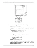
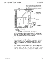
4. Remove the screw holding the current loop option to the motherboard.
5. Disconnect the current loop option PCA from the appropriate connector on the
motherboard (see Figure 3-10).
6. Each connector, J19 and J23, requires two shunts. Place one shunt on the two left-
most pins and the second shunt on the two pins next to it (see Figure 3-10).
7. Reattach the top case to the analyzer.
•
T
he
analyzer is now ready to have a voltage-sensing, recording device attached
to that output.
8. Calibrate the analog output as described in Section 5.9.3.2.
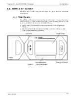
3.3.1.5.
CONNECTING THE STATUS OUTPUTS
The status outputs report analyzer conditions via optically isolated NPN transistors,
which sink up to 50 mA of DC current. These outputs can be used interface with
devices that accept logic-level digital inputs, such as Programmable Logic Controllers
(PLCs). Each status bit is an open collector output that can withstand up to 40 VDC.
All of the emitters of these transistors are tied together and available at D.
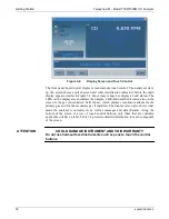
ATTENTION
COULD DAMAGE INSTRUMENT AND VOID WARRANTY
Most PLC’s have internal provisions for limiting the current that the input
will draw from an external device. When connecting to a unit that does
not have this feature, an external dropping resistor must be used to limit
the current through the transistor output to less than 50 mA. At 50 mA, the
transistor will drop approximately 1.2V from its collector to emitter.
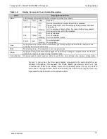
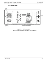
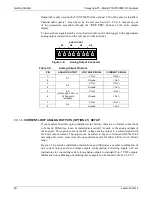
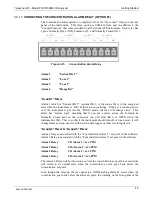
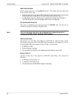
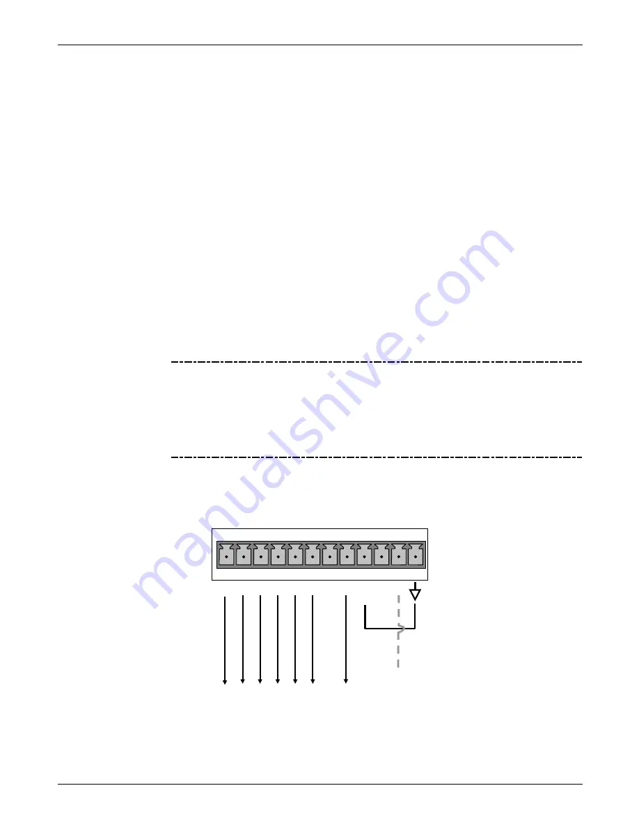
The status outputs are accessed via a 12-pin connector on the analyzer’s rear panel
labeled STATUS (see Figure 3-4). Pin-outs for this connector are:
STATUS
1 2 3 4 5 6 7 8 D
+
SY
ST
E
M
OK
HI
G
H RANG
E
CO
NC V
AL
ID
Z
E
RO
CAL
S
P
A
N CAL
DI
AG
M
O
D
E
O
p
ti
o
n
a
l
O
2
CAL
+5V to external device
Figure 3-11:
Status Output Connector
06864D DCN7562
Содержание T300
Страница 2: ......
Страница 4: ...Teledyne API Model T300 T300M CO Analyzer ii This page intentionally left blank 06864D DCN7562 ...
Страница 80: ...Getting Started Teledyne API Model T300 T300M CO Analyzer 78 This page intentionally left 06864D DCN7562 ...
Страница 134: ...Setup Menu Teledyne API Model T300 T300M CO Analyzer 132 This page intentionally left blank 06864D DCN7562 ...
Страница 182: ...06864D DCN7562 ...
Страница 190: ...Remote Operation Teledyne API Model T300 T300M CO Analyzer 188 This page intentionally left blank 06864D DCN7562 ...
Страница 227: ...225 This page intentionally left blank 06864D DCN7562 ...
Страница 228: ...06864D DCN7562 ...
Страница 320: ...INDEX Teledyne API Model T300 T300M CO Analyzer 318 This page intentionally left blank 06864D DCN7562 ...
Страница 347: ...Appendix B Schematic 06864D DCN7562 ...


