


Teledyne API – Model T300/T300M CO Analyzer
Troubleshooting and Service
257
11.4.
OTHER PERFORMANCE PROBLEMS
Dynamic problems (i.e. problems which only manifest themselves when the analyzer is
monitoring sample gas) can be the most difficult and time consuming to isolate and
resolve. The following provides an itemized list of the most common dynamic problems
with recommended troubleshooting checks and corrective actions.
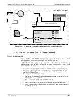
11.4.1.
TEMPERATURE PROBLEMS
Individual control loops are used to maintain the set point of the absorption bench, filter
wheel and IR photo-detector temperatures. If any of these temperatures are out of range
or are poorly controlled, the T300/T300M will perform poorly.
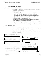
11.4.1.1.
BOX OR SAMPLE TEMPERATURE
B
OX
T
EMPERATURE
The box temperature sensor is mounted to the motherboard and cannot be disconnected
to check its resistance. Rather check the
BOX TEMP
signal using the SIGNAL I/O
function under the
DIAG
Menu (See Section 5.9.1). This parameter will vary with
ambient temperature, but at ~30
o
C (6-7° above room temperature) the signal should be
~1450 mV.
S
AMPLE
T
EMPERATURE
The Sample Temperature should closely track the bench temperature. If it does not,
locate the sensor, which is located at the midpoint of the optical bench in a brass fitting.
Unplug the connector labeled “Sample”, and measure the resistance of the thermistor; at
room temperature (25°C) it should be ~30K Ohms, at operating temperature, 48°C, it
should be ~ 12K Ohms
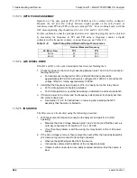
11.4.1.2.
BENCH TEMPERATURE
There are three possible failures that could cause the Bench temperature to be incorrect.
1. The heater mounted to the bottom of the Absorption bench is electrically shorted or
open.
•
Check the resistance of the two heater elements by measuring between pin 2 and
4 (~76 Ohms), and pin 3 and 4 (~330 Ohms), of the white five-pin connector just
below the sample temperature sensor on the Bench (pin 1 is the pointed end).
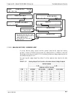
2. Assuming that the I
2
C bus is working and that there is no other failure with the relay
board, the solid-state relay (K2) on the relay board may have failed.
•
Using the BENCH_HEATER parameter under the signal I/O function, as
described above, turn on and off K2 (D3 on the relay board should illuminate as
the heater is turned on).
•
Check the AC voltage present between pin 2 and 4, for a 100 or 115 VAC
model, and pins 3 and 4, for a 220-240 VAC model.
WARNING
-
E
LECTRICAL
S
HOCK
H
AZARD
Hazardous Voltages are present during this test.
06864D DCN7562
Содержание T300
Страница 2: ......
Страница 4: ...Teledyne API Model T300 T300M CO Analyzer ii This page intentionally left blank 06864D DCN7562 ...
Страница 80: ...Getting Started Teledyne API Model T300 T300M CO Analyzer 78 This page intentionally left 06864D DCN7562 ...
Страница 134: ...Setup Menu Teledyne API Model T300 T300M CO Analyzer 132 This page intentionally left blank 06864D DCN7562 ...
Страница 182: ...06864D DCN7562 ...
Страница 190: ...Remote Operation Teledyne API Model T300 T300M CO Analyzer 188 This page intentionally left blank 06864D DCN7562 ...
Страница 227: ...225 This page intentionally left blank 06864D DCN7562 ...
Страница 228: ...06864D DCN7562 ...
Страница 320: ...INDEX Teledyne API Model T300 T300M CO Analyzer 318 This page intentionally left blank 06864D DCN7562 ...
Страница 347: ...Appendix B Schematic 06864D DCN7562 ...