


156 Description Of Specific Functions
V260 Series High Performance Closed-Loop Vector Inverter User Manual
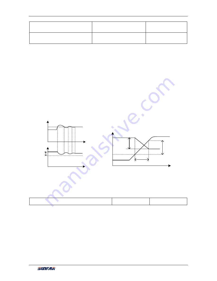
F5.3.41 Load balancing
adjustment gain
Setting range: 0.0~100.00
Factory default:50.00
F5.3.42 Load balancing
adjustment limit
Setting range:0.00~100.00(%)
Factory default:1.00
Load dynamic balance function is used for balancing load with multiple motors linkage, or
occasions
requiring torque motor characteristics of "Frequency inverter-asynchronous electrical units".
When this function is valid, frequency inverter shall take the input value of dynamic balance load reference
source (relative value of rated current) as reference, automatically amend the input of frequency/revolving
speed integrator, adjusting output frequency to balance the load. The adjustment to output frequency for
dynamic balance function is relatively slow, and influenced by selections of acceleration and deceleration
time.
If rapid response of linkage balance operation is required, please apply with linkage operation self-balancing
function (referring to instruction of parameters in FA group), or applying with compensation PID to build
flexibly as necessary, which can conduct adjustment directly to the output of frequency integrator.
Adjusting gain value = [F5.3.41]*rated current of equipment/100, when the difference of output current and
reference value reaches the adjusting gain value, output frequency will drop to the adjusting amplitude limit
value.
Adjusting amplitude limit value = [F5.3.42]*current selected frequency/100, this value is the amplitude peak
of dynamic balance adjustment.
Frequency
Reference load
(F5.3.39)
[F5.3.42]
Time
Time
Load
Adjusting
gain value
Adjusting area
Output voltage
Reference
value
Adjusting
limit
Output
frequency
t
7.25 MOTOR TEMPERATURE DETECTION (GROUP F5.4)
F5.4.43 Type 2 of motor temperature sensor
Setting range: 0~6
Factory default: 0
This parameter is referred to types of the selected motor temperature sensor; the different selected motor
temperatures sensor with different internal algorithms results in corresponding changes in units of
F5.4.46
and
F5.4.47
: When the sensor is the thermoswitch/
PT100
, their units are
℃
; When the sensor is
PTC
, their
units are
Ω
0: None 1: 1 X PT100
2: 2 X PT100 3: 3 X PT100
4: PTC sensor 5: Thermo switch (normally closed)
6: Thermo switch (normally open)
The motor temperature can be measured by connecting the PT100 or PTC sensor to the analog input and
output interfaces of frequency converter. See Figure 7-47-A and Figure 7-47-B for wiring:
Figure 7-45 Sketch of load dynamic balance function
Figure 7-46 Sketch of dynamic balance variables


