2
| Optidrive P2 User Guide |
Version 3.07
www.invertekdrives.com
1. Quick Start Up . . . . . . . . . . . . . . . . . . . . . . . . . . . .
1.1. Important Safety Information . . . . . . . . . . . . . . . . . . . .
1.2. Quick Start Process . . . . . . . . . . . . . . . . . . . . . . . . . . . .
2. General Information and Ratings . . . . . . . . . . .
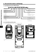
2.1. Identifying the Drive by Model Number . . . . . . . . . .
2.2. Product Rating Label Location . . . . . . . . . . . . . . . . . . .
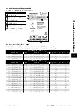
2.3. Understanding the Rating Label . . . . . . . . . . . . . . . . .
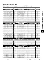
2.4. Drive Model Numbers – IP20 . . . . . . . . . . . . . . . . . .
2.5. Drive Model Numbers – IP55 . . . . . . . . . . . . . . . . . .
2.6. Drive Model Numbers – IP66 Non-switched . . . . .
2.7. Drive Model Numbers – IP66 Switched . . . . . . . . . .
3. Mechanical Installation . . . . . . . . . . . . . . . . . . . .
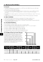
3.1. General . . . . . . . . . . . . . . . . . . . . . . . . . . . . . . . . . . . . . .
3.2. Before Installation . . . . . . . . . . . . . . . . . . . . . . . . . . . . .
3.3. UL Compliant Installation . . . . . . . . . . . . . . . . . . . . . . .
3.4. Installation Following a Period of Storage . . . . . . . .
3.5. Mechanical Dimensions and Weight . . . . . . . . . . . .
3.6. Guidelines for Enclosure Mounting (IP20 Units) . . . . .
3.7. Mounting the Drive – IP20 Units. . . . . . . . . . . . . . . . . . .
3.8. Guidelines for Mounting (IP55 Units) . . . . . . . . . . . .
3.9. Guidelines for Mounting (IP66 Units) . . . . . . . . . . . .
3.10. Removing the Terminal Cover . . . . . . . . . . . . . . . . . . .
3.11. Routine Maintenance . . . . . . . . . . . . . . . . . . . . . . . . . .
4. Electrical Installation . . . . . . . . . . . . . . . . . . . . . . . 20
4.1. Connection Diagram . . . . . . . . . . . . . . . . . . . . . . . . . . . 20
4.2. Protective Earth (PE) Connection . . . . . . . . . . . . . . . . .
4.3. Incoming Power Connection . . . . . . . . . . . . . . . . . . . .
4.4. Operation of 3 Phase drives from a Single Phase
Supply . . . . . . . . . . . . . . . . . . . . . . . . . . . . . . . . . . . . . . . . . . .
4.5. Operation with DC Power Supply or Common DC
Bus . . . . . . . . . . . . . . . . . . . . . . . . . . . . . . . . . . . . . . . . . . . . . .
4.6. Motor Connection. . . . . . . . . . . . . . . . . . . . . . . . . . . . .
4.7. Motor Terminal Box Connections . . . . . . . . . . . . . . . .
4.8. Connecting a Brake Resistor . . . . . . . . . . . . . . . . . . . .
4.9. Control Terminal Wiring . . . . . . . . . . . . . . . . . . . . . . . .
4.10. Control Terminal Connections . . . . . . . . . . . . . . . . . . 26
4.11. IP66 Switched Version Integrated Control Switch
and Potentiometer Wiring . . . . . . . . . . . . . . . . . . . . . . . . . .
4.12. Motor Thermal Overload Protection . . . . . . . . . . . . .
4.13. EMC Compliant Installation . . . . . . . . . . . . . . . . . . . . 28
4.14. Safe Torque Off . . . . . . . . . . . . . . . . . . . . . . . . . . . . . . 29
5. Keypad and Display Operation . . . . . . . . . . . . . . . . . . . . . . 33
5.1. Keypad and Display Layout . . . . . . . . . . . . . . . . . . . . . . . . . . . . . . . 33
5.2. Selecting the Language on the TFT Display . . . . . . . . . . . . . . . . . 33
5.3. Additional Display Messages . . . . . . . . . . . . . . . . . . . . . . . . . . . . . 34
5.4. Changing Parameters . . . . . . . . . . . . . . . . . . . . . . . . . . . . . . . . . . . . 35
5.5. Parameter Factory Reset / User Reset . . . . . . . . . . . . . . . . . . . . . . 35
5.6. Resetting the Drive Following a Trip . . . . . . . . . . . . . . . . . . . . . . . . 35
5.7. Keypad Shortcuts . . . . . . . . . . . . . . . . . . . . . . . . . . . . . . . . . . . . . . . . 36
6. Parameters . . . . . . . . . . . . . . . . . . . . . . . . . . . . . . . . . . . . . . .
6.1. Parameter Set Overview . . . . . . . . . . . . . . . . . . . . . . . . . . . . . . . . . . .
6.2. Parameter Group 1 – Basic Parameters . . . . . . . . . . . . . . . . . . . . . .
7. Control Terminal Functions . . . . . . . . . . . . . . . . . . . . . . . . . . . 40
7.1. Control Source Selection . . . . . . . . . . . . . . . . . . . . . . . . . . . . . . . . . . 40
7.2. Digital Input Configuration Parameter P1-13. . . . . . . . . . . . . . . . . . . 42
7.3. Example Connection Schematics . . . . . . . . . . . . . . . . . . . . . . . . . . . . 43
8. Extended Parameters . . . . . . . . . . . . . . . . . . . . . . . . . . . . . .
8.1. Parameter Group 2 - Extended Parameters . . . . . . . . . . . . . . . . . . . . 47
8.2. Parameter Group 3 – PID Control . . . . . . . . . . . . . . . . . . . . . . . . . . . 52
8.3. Parameter Group 5 – Communication Parameters . . . . . . . . . . . . . 56
8.4. Advanced Parameters . . . . . . . . . . . . . . . . . . . . . . . . . . . . . . . . . . . . . 58
8.5. Parameter Group 0 – Monitoring Parameters (Read Only) . . . . . . 62
9. Serial Communications . . . . . . . . . . . . . . . . . . . . . . . . . . .
9.1. RS-485 Communications . . . . . . . . . . . . . . . . . . . . . . . . . . . . . . . . . 64
9.2. Modbus RTU Communications . . . . . . . . . . . . . . . . . . . . . . . . . . . . . . 65
9.3. CAN Open Communication . . . . . . . . . . . . . . . . . . . . . . . . . . . . . . . 67
10. Technical Data . . . . . . . . . . . . . . . . . . . . . . . . . . . . . . . . .
10.1. Environmental . . . . . . . . . . . . . . . . . . . . . . . . . . . . . . . . . . . . . . . . . . .
10.2. Input/Output Power and Current Ratings . . . . . . . . . . . . . . . . . . . .
10.3. Input Power Supply Requirements . . . . . . . . . . . . . . . . . . . . . . . . . .
10.4. Additional Information for UL Approved Installations . . . . . . . . . . .
10.5. Derating Information . . . . . . . . . . . . . . . . . . . . . . . . . . . . . . . . . . . . .
10.6. Internal EMC Filter and Varistors – Disconnection Procedure . . . .
11. Troubleshooting . . . . . . . . . . . . . . . . . . . . . . . . . . . . . . . .
11.1. Fault Messages . . . . . . . . . . . . . . . . . . . . . . . . . . . . . . . . . . . . . . . . . .
12. Energy Efficiency Classification . . . . . . . . . . . . . . . . . . .


