56
| Optidrive P2 User Guide |
Version 3.07
www.invertekdrives.com
Par
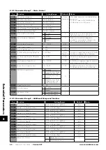
Parameter Name
Minimum
Maximum
Default
Units
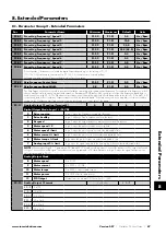
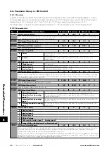
P4-08 Minimum Torque Limit
P4-08
150
0
%
Active only in Vector Speed or Vector Torque motor control modes (P4-01 = 0 or 1). Sets a minimum torque limit, whereby when the
Optidrive is enabled, it will always attempt to maintain this torque on the motor at all times whilst operating.
NOTE This parameter should be used with extreme care, as the drive output frequency will increase to
achieve the torque level, and may exceed the selected speed reference.
P4-09 Regenerative Torque Limit
0.0
500
100
%
Active only in Vector Speed or Vector Torque motor control modes (P4-01 = 0 or 1). Sets the maximum regenerating torque allowed by
the Optidrive.
P4-10
V/F Characteristic Adjustment Frequency
0.0
P1-09
0.0
Hz
When operating in V/F mode (P4-01 = 2), this parameter in conjunction with P4-11 sets a frequency point at which the voltage set in
P4-11 is applied to the motor. Care must be taken to avoid overheating and damaging the motor when using this feature.
P4-11
V/F Characteristic Adjustment Voltage
0
P1-07
0
V
Used in conjunction with parameter P4-10.
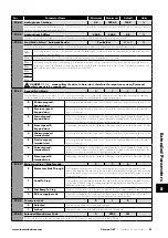
P4-12
Thermal Overload Retention
0
1
1
-
0
Disabled
1
Enabled
All Optidrives feature electronic thermal overload protection for the connected motor, designed to protect
the motor against damage. An internal overload accumulator monitors the motor output current over time,
and will trip the drive if the usage exceeds the thermal limit. When P4-12 is disabled, removing the power
supply from the drive and re-applying will reset the value of the accumulator. When P4-12 is enabled, the
value is retained during power off.
P4-13
Output Phase Sequence
0
1
0
-
0
U,V,W
Stand motor phase sequence. Typically, this provides clockwise rotation of the motor.
1
U,W,V
Reverse motor phase sequence. Typically this provides counter-clockwise rotation of the motor.
P4-14
Thermal Overload Reaction
0
1
0
-
0
Trip
When the overload accumulator reaches the limit, the drive will trip on It.trp to prevent damage to the motor.
1
Current
Limit
Reduction
When the overload accumulator reaches 90% of, the output current limit is internally reduced to 100%
of P1-08 in order to avoid an It.trp. The current limit will return to the setting in P4-07 when the overload
accumulator reaches 10%.
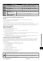
P4-15
Master Mode Configuration (Master-Slave Mode)
0
1
0
-
0
Motor speed
& torque
reference
In this mode, when the drive functions as a Master in Master-Slave Mode, the data broadcast on the drive
network is the Master Actual Speed and the Master Torque Reference. This mode is suitable for Master-
Slave applications which required speed following.
1
Speed
reference &
motor torque
In this mode, when the drive functions as a Master in Master-Slave Mode, the data broadcast on the drive
network is the Master Speed Reference and the Master Actual Torque. This mode is suitable for Master-
Slave applications which required load sharing between multiple drives.
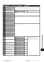
8.3. Parameter Group 5 – Communication Parameters
8.3.1. Overview
Optidrive P2 provides many methods to allow the user to connect to a variety of fieldbus networks. In addition, connection to options
such as external keypads, PC and Optistick are possible. Parameter Group 5 provides the parameters required to configure the
various fieldbus interfaces and connection points.
8.3.2. Connecting Invertek Drives Options
All Invertek Drives options which require communication with the drive, such as the Optiport and Optipad remote keypads and
Optistick connect to the Optidrive P2 using the built in RJ45 connection point. The pin connections on these options are already
matched, such that a simple pin to pin plug in cable can be used to connect these options without any special requirements.
For further information on connecting and using these optional items, refer to the specific option User guide.
8
Extended P
arameters


