24
| Optidrive P2 User Guide |
Version 3.07
www.invertekdrives.com
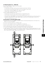
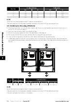
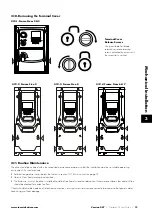
4.8. Connecting a Brake Resistor
Optidrive P2 units feature an internal brake transistor, fitted as standard for all models. The brake resistor should be connected to the
DC+ and BR terminals of the drive. These terminals are shrouded, and the shrouding should be removed to access the terminals.
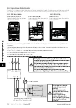
4.8.1. IP20 Drive Models
4.8.2. IP55 & IP66
Frame Sizes 2, 3, 4 & 5
Remove the plastic cover from the base
of the drive as indicated.
Frame Sizes 6A/ 6B
Remove the plastic cover from inside the
drive as indicated.
EMC
EMC
VAR
AC
DC
All frame sizes
Remove the plastic cover from inside the
drive as indicated.
L1
L3
EMC
L2/N
U
V
W
1 2 3 4 5 6 7 8 9 10 11 12 13
14 15 16 17 18
I0I0I
I0I0I
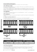
The brake transistor is enabled using P1-05 (Refer to section
6.2. Parameter Group 1 – Basic Parameters
information).
Software protection against brake resistor overload is carried out within the drive. For correct protection of the brake resistor, the
following settings are required:
Set P1-14 = 201 (where 201 is the default password setting for advanced parameter access).
Enter the resistance of the brake resistor in P6-19 (Ohms).
Enter the power of the brake resistor in P6-20 (kW).
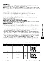
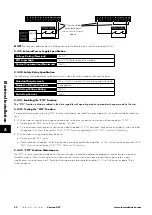
Dynamic Brake Resistor with Thermal Overload Protection
L1/L
K1
ODP-2
DC+
K1 - Main Contractor
Thermal Overload / Brake Resistor
with internal Over Temperature switch
BR
L2/N
L3
Dlx
+ 24 VDC
ODP-2
Optional wiring
It is highly recommended to equip the drive with a main
contactor in order to provide an additional thermal overload
protection for the braking resistor.
The contactor should be wired so that it will open when the
resistor overheats, otherwise the drive will not be able to
interrupt the main supply if the brake chopper remains closed
(short-circuited) in a fault situation.
It is also recommended to wire the thermal overload
protection to a digital input of the drive as an External Trip.
The voltage level at these
terminals may exceed
800V DC.
Stored charge may be
present after disconnecting
the mains power.
Allow a minimum of 5
minutes discharge after
power off before attempting
any connection to these
terminals.
4
Elec
trical Installation


