Version 3.07
| Optidrive P2 User Guide |
65
www.invertekdrives.com
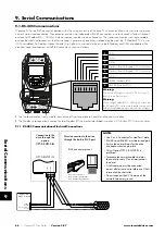
Modbus RTU and CANbus connection should be made via the RJ45 connector. The pin assignments are as shown above, in section
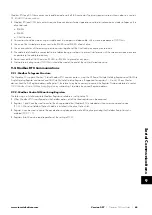
Modbus RTU and CANbus networks require three conductors for best operation and to eliminate common mode voltages on the
drive terminals:
o RS485+
o RS485-
o 0 Volt Common
Connection should be made using a suitable dual twisted pair, shielded cable, with a wave impedance of 120 Ohms.
Use one of the twisted pairs to connect to the RS485+ and RS485- of each drive.
Use one conductor of the remaining pair to connect together all the 0 volt common connection terminals.
The cable shield should be connected to a suitable clean ground point to prevent interference with the screen maintained as close
as possible to the cable terminations.
Do not connect the 0 Volt Common, RS485- or RS485+ to ground at any point.
Network terminating resistor (120 Ohms) should be used at the end of the network to reduce noise.
9.2. Modbus RTU Communications
9.2.1. Modbus Telegram Structure
The Optidrive P2 supports Master / Slave Modbus RTU communications, using the 03 Read Multiple Holding Registers and 06 Write
Single Holding Register commands and 16 Write Multiple Holding Registers (Supported for registers 1 – 4 only). Many Master
devices treat the first Register address as Register 0; therefore it may be necessary to convert the Register Numbers detailed in section
9.2.2. Modbus Control & Monitoring Registers
by subtracting 1 to obtain the correct Register address.
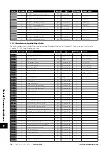
9.2.2. Modbus Control & Monitoring Registers
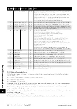
The following is a list of accessible Modbus Registers available in the Optidrive P2.
When Modbus RTU is configured as the Fieldbus option, all of the listed registers can be accessed.
Registers 1 and 2 can be used to control the drive provided that Modbus RTU is selected as the primary command source
(P1-12 = 4) and no Fieldbus Option Module is installed in the drive Option Slot.
Register 4 can be used to control the acceleration and deceleration rate of the drive providing that Fieldbus Ramp Control is
enabled (P5-07 = 1).
Registers 6 to 24 can be read regardless of the setting of P1-12.
9
Serial Communications

