112
Water circulation & temperature regulation (for DHW)
Piping diameter
Total length of straight pipe between boiler & tank
Number of elbows
Number of tees
Temperature rise between inlet and outlet after 5 min. cold-start operating max. power
°C / °F
Water temperature setpoint
Test of Water Flow Switch (DHW)?
(Yes/NO)
Combustion settings
unit:
Set for NG (Natural Gas) or LP (Liquid Propane)?
NG or LPG?
If LPG is the right gas orifice mounted?
(YES/NO)
Diameter gas orifice for LPG?
mm
CO2 / O2 level at high fire …%
%
CO2 / O2 level on low fire …%
%
Flue pressure @ CO2 / O2 measuring point at high fire
Pa
Flue pressure @ CO2 / O2 measuring point at low fire
Pa
If cascaded with common flue system run all appliances at high fire and
measure Flue pressure
Pa
If cascaded with a common flue system; run all appliances, measure the
flue pressure at low- and at high fire.
Pa
Additives
Used chemical additions
Mixing Ratio
Gas supply
Type of Gas from installation
Is gas isolation valve installed under boiler according to installation manual?
(YES/NO)
Which diameter gas isolation valve is installed?
Gas piping (inside) diameter
Gas piping material (if possible specify mark/type)
Gas piping flexible (YES/NO)
(YES/NO)
Gas piping inside structure (e.g. smooth/corrugated)
Measured Gas pressure @Gas valve (Static) **
Measured Gas pressure @Gas valve (dynamic - all gas appliances in the building
should be turned on and running at full load)
Is there a secondary gas pressure regulator before the boiler?
(YES/NO)
If YES what is the length of the Gas piping in between?
If YES what is the Brand & Model?
Electronics & Power supply
unit:
Version Burner Controller Hardware (see Chapter 3.2 for location)
Version Burner Controller Firmware (see Chapter 3.2 for location)
is ground connected to building grounding system
(YES/NO)
Voltage incoming (Hot to Neutral)
V
Voltage incoming (Hot to Neutral)
V
Voltage measured between Ground and Neutral
V
Total of amperage switched by the Boiler Control is below 3.5 A or 800 W
A
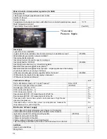
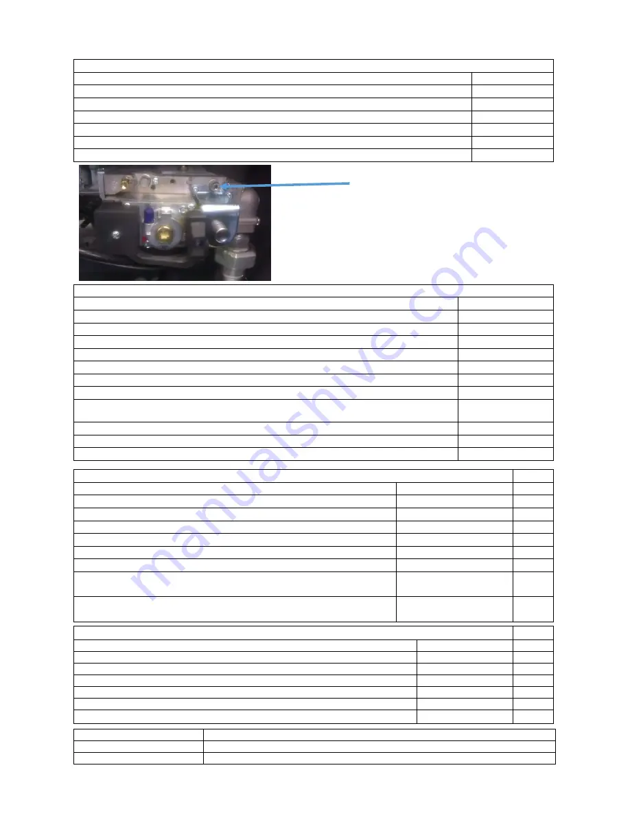
**Gas valve
Pressure Nipple
Содержание S-CBX 105
Страница 2: ......
Страница 40: ...40 9 10 Flue Terminal Positioning ...
Страница 42: ...42 9 11 1 FIGURE 12 LINE G ...
Страница 55: ...55 11 5 Ladder Logic Diagram ...
Страница 56: ...56 11 6 Electrical schematics ...
Страница 57: ...57 ...
Страница 137: ......

