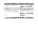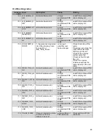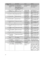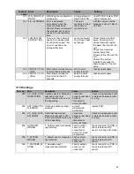
77
12.8.6 D
ISPLAY MENU STRUCTURE SUMMARY
.
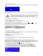
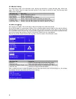
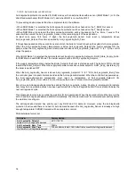
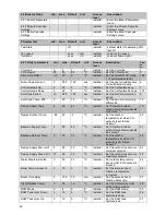
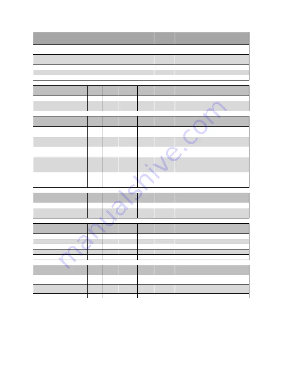
Menu Structure Display:
Access
level
Description:
1. Central Heating (CH)
User
Enter the Central Heating (CH)
menu
2. Domestic Hot Water (DHW)
User
Enter the Domestic Hot Water
(DHW) menu
3. Information
User
Enter the Information menu
4. Settings
User
Enter the Settings menu
5. System Test
User
Enter the System Test menu
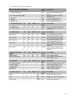
1. Central Heating (CH) min. max. Default unit
Access
level
Description:
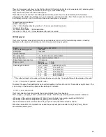
1.1 CH Setpoint
20
90
85
°C
Installer Set the CH setpoint if CH mode is 0
1.2 Outdoor Reset
User
Enter the Outdoor Reset menu if
CH mode is 1
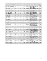
1.2 Outdoor reset
min.
max.
Default
unit
Access
level
Description:
Des. Supply T.
20
90
85
°C
Installer Set CH setpoint when outdoor
temperature equals Des. Outd. T.
Bas. Supply T.
20
90
40
°C
Installer Set CH setpoint when outdoor
temperature equals Bas. Outd. T.
WW Shutdown
0
35
22
°C
Installer Set outdoor temperature above
which CH demand is locked.
Bas. Outd. T.
0
30
20
°C
Installer Set the outdoor temperature at
which CH setpoint is set to Bas.
Supply T.
Des. Outd. T.
-25
25
-5
°C
Installer Set the outdoor temperature at
which CH setpoint is set to Des.
Supply T.
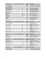
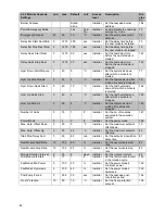
2. Domestic Hot Water
(DHW)
min.
max.
Default
unit
Access
level
Description:
DHW Setpoint
40
71
60
°C
Installer Set the DHW setpoint
DHW Store Setpoint
40
71
65
°C
Installer Set the DHW store setpoint for
DHW mode 1 and 2
3. Information
min.
max.
Default
unit
Access
level
Description:
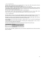
3.1 Software versions
User
Enter the Software Versions menu
3.2 Boiler Status
User
Enter the Boiler Status menu
3.3 Boiler History
User
Enter the Boiler History menu
3.4 Error Log
User
Enter the Error Log menu
3.5 Service
User
Enter the Service menu
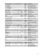
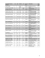
3.1 Software versions
min.
max.
Default
unit
Access
level
Description:
Display
xxxx
xxxx
User
Display the software checksum
Boiler
xxxx
xxxx
User
Display the boiler software checksum
Device Group
xxxMN
User
Display the boiler group ID
Содержание S-CBX 105
Страница 2: ......
Страница 40: ...40 9 10 Flue Terminal Positioning ...
Страница 42: ...42 9 11 1 FIGURE 12 LINE G ...
Страница 55: ...55 11 5 Ladder Logic Diagram ...
Страница 56: ...56 11 6 Electrical schematics ...
Страница 57: ...57 ...
Страница 137: ......

