3-20
Expansion Board Installation
Chapter 3 - Installation
STARPLUS STSe - Installation Manual
August 2005
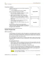
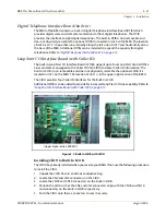
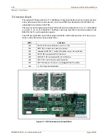
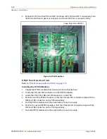
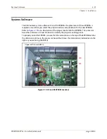
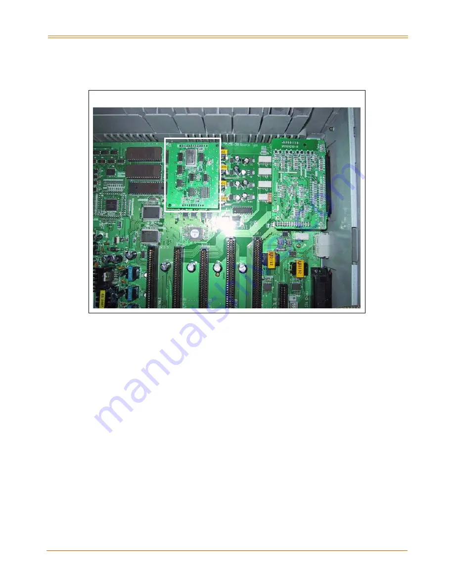
5. Position the PLLU so that CN2 and CN1 match up with CN14 and CN15 respectively. Push
the PLLU onto their respective connectors and ensure the PLLU is seated correctly.
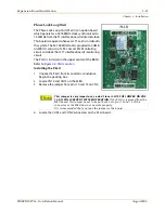
Figure 3-8: PLLU Location
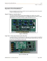
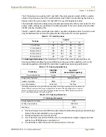
DTMF Tone Detection Units
Refer to
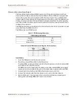
“T1IB (24 channel) with two DTRUs” on page 3-16
.
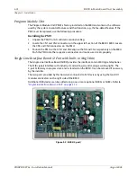
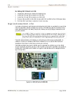
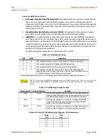
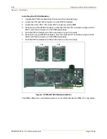
Installing the DTRU4 Modules
1. Unpack the DTRU4 modules from their antistatic conductive bags.
2. Locate the CN1 and CN2 connectors on the DTRU4 modules.
3. Locate the CN4, CN5, CN8 and CN9 connectors on the T1IB.
4. Position one of the DTRU4 modules so that the CN2 and CN1 connectors align with the
CN8 and CN9 connectors on the T1IB respectively.
5. Push the DTRU4 module onto these connectors to seat it securely.
6. Position the second DTRU4 module so that the CN2 and CN1 connectors align with the
CN4 and CN5 connectors on the T1IB respectively.
7. Push the DTRU4 module onto these connectors to seat it securely.
PLL
U
CID
U
(Upper Right View of BKSU)
Содержание STSe Key System
Страница 1: ...August 2005 Issue 1 0 STARPLUS STSe Key Systems Installation Manual TM...
Страница 4: ......
Страница 10: ...vi Figures STARPLUS STSe Installation Manual August 2005...
Страница 12: ...viii Tables STARPLUS STSe Installation Manual August 2005...
Страница 14: ...N O T E S...
Страница 22: ...N O T E S...
Страница 30: ...N O T E S...
Страница 68: ...3 40 Door Box Chapter 3 Installation STARPLUS STSe Installation Manual August 2005...
Страница 70: ...N O T E S...
Страница 94: ...iv Index STARPLUS STSe Installation Manual August 2005...

