3-12
BKSU & Main Board Unit Assembly
Chapter 3 - Installation
STARPLUS STSe - Installation Manual
August 2005
Program Module Unit
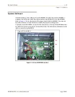
The Program Module Unit (PMU) is factory-installed on the MBU and contains the software
used by the system to control features and their function, e.g., the fax-detect feature. If the
PMU must be replaced, use the following procedure.
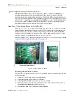
Installing the PMU
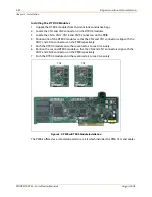
1. Unpack the PMU from its antistatic conductive bag.
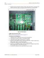
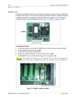
2. Locate the CN1 and CN2 connectors on the upper left section of the BKSU’s MBU. Locate
the CN1 and CN2 connectors on the PMU.
3. Position the PMU so that CN1 and CN2 align withCN1 and CN2 respectively on the MBU.
Push the PMU onto the respective connectors and make sure it seats properly.
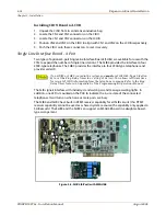
Single Line Interface Board (2 Port with built-in Msg Wait)
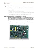
The Single Line Interface Board (SLIB2) provides the interface to two 2500-type telephones.
The SLIB signals interface with industry-standard ringers and message waiting lights. The
2-port SLIB always occupies slot 2 and is standard on the BKSU. It can be removed if necessary
by the installer.
The two ports provided by this board are connected to SLT devices by using the two RJ11
modular connectors on the right side of the BKSU.
Additional SLIB devices can be added using one or more optional SLIB4s or SLIBCs. Refer to
“Single Line Interface Board - 4 Port” on page 3-14
Figure 3-2: SLIB2 (2 port)
Содержание STSe Key System
Страница 1: ...August 2005 Issue 1 0 STARPLUS STSe Key Systems Installation Manual TM...
Страница 4: ......
Страница 10: ...vi Figures STARPLUS STSe Installation Manual August 2005...
Страница 12: ...viii Tables STARPLUS STSe Installation Manual August 2005...
Страница 14: ...N O T E S...
Страница 22: ...N O T E S...
Страница 30: ...N O T E S...
Страница 68: ...3 40 Door Box Chapter 3 Installation STARPLUS STSe Installation Manual August 2005...
Страница 70: ...N O T E S...
Страница 94: ...iv Index STARPLUS STSe Installation Manual August 2005...


