Expansion Board Installation
3-17
Chapter 3 - Installation
STARPLUS STSe - Installation Manual
August 2005
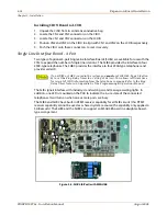
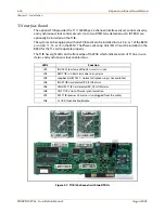
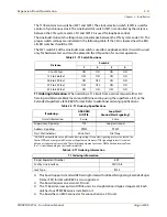
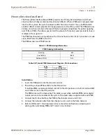
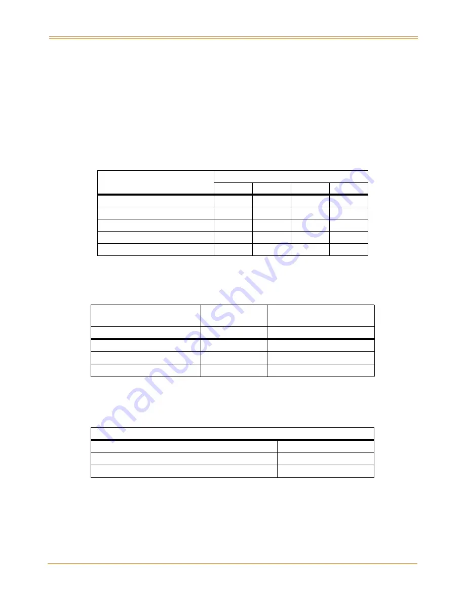
The T1IB contains two switches (SW1 and SW3). The clock selection switch (SW3) is used for
control of synchronous clock. The Line Build-Out switch (SW1) is controlled by the distance
between the
STSe
system and a CSU and SW1 #4 is used for loopback control.
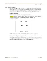
The Line Build-Out switch setting is based on distance between the
STSe
System and a CSU. The
proper switch settings are indicated in the following table. If the CSU is located near the KSU,
all LBO switches should be ON.
The SW1 switch #4 of the Line Build-Out switch is used for Loopback control. Its switch is used
only for hardware test and must be placed in the ON position for normal operation.
T1 Ordering Information:
When ordering a T1 circuit from a carrier, request either D4
framing and Alternate Mark Inversion (AMI) Line coding using the superframe (SF), or the
Extended Superframe (ESF-B8ZS) format. Refer to additional ordering specifications:
This board supports standard D4 framing format with robbed bit signaling. Extended Super
Frame (ESF) format with B8ZS is also supported.
The board requires an external CSU unit.
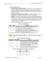
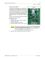
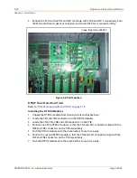
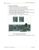
The T1 board can accept two DTRU4 units in a daughter board type arrangement. Each
unit has four DTMF Receivers installed on it.
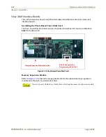
The board has an RJ45 connector for connection to a CSU unit.
Table 3-1: T1 Switch Positions
Distance
Switch #
1
2
3
4
0 to 133 feet
ON
ON
ON
ON
133 to 266 feet
OFF
ON
ON
ON
266 to 399 feet
ON
OFF
ON
ON
399 to 533 feet
OFF
OFF
ON
ON
533 to 655 feet
ON
ON
OFF
ON
Table 3-2: T1 Ordering Specifications
If ordering…
ANI/DNIS/
DID/TIE
Loop Start/
Ground Start Signaling*
Circuit Information
2 wire
2 wire
Supervisory Signaling
TIE
Loop or Ground
Address Signaling
DTMF
DTMF
Start Dial Indicator
Wink Start
Dial Tone
* ANI/DNIS not available on Loop/Ground start signaling. If Loop Start signaling protocol is ordered, the
Central Office does not provide Disconnect Supervision. However if TIE signaling protocol is ordered,
disconnect supervision is provided. The switching equipment processes DNIS numbers received from
the T-1 circuit depending on the trunk simulation.
Table 3-3: T1 Ordering Information
T1 Ordering Information
Ringer Equivalent Number
6.0P
Facility Line Interface
04DU9-B
Jack Type
RJ45
Содержание STSe Key System
Страница 1: ...August 2005 Issue 1 0 STARPLUS STSe Key Systems Installation Manual TM...
Страница 4: ......
Страница 10: ...vi Figures STARPLUS STSe Installation Manual August 2005...
Страница 12: ...viii Tables STARPLUS STSe Installation Manual August 2005...
Страница 14: ...N O T E S...
Страница 22: ...N O T E S...
Страница 30: ...N O T E S...
Страница 68: ...3 40 Door Box Chapter 3 Installation STARPLUS STSe Installation Manual August 2005...
Страница 70: ...N O T E S...
Страница 94: ...iv Index STARPLUS STSe Installation Manual August 2005...

