


1-30E
124
Tusa
0015
TV COMM
0035, 0019
TV Guide
1476
TV86
0063, 0040
Uniden
0022, 0225
Unika
0207, 0153, 0022
United Artists
0007
United Cable
0003, 0014, 0011, 0276
Universal
0191, 0078, 0207, 0056,
0022, 0039, 0153, 0077,
0322, 0315
US Electronics
0276, 0008, 0003, 0017
V2
0883
Verizon
0246
Videoway
0250, 0000
VideoWorks
0124
Vidtech
0244
Viewmaster
0883, 0770
Viewstar
0258, 0289, 0060, 0063,
0211, 0027, 0111, 0030,
0121
Vision
0883
Visionetics
1264
Vortex View
0883
WaveMaster
0565
Wiso
0078
Zenith
0000, 0525, 0054, 0017,
0039, 0153, 0060, 0315,
0191, 0899
Zentek
0400
Cable box brand
Code number
Satellite receiver
brand
Code number
AlphaStar
0772
Atlantic Telephone
1333
Bell ExpressVu
0775
Century
0856
Chaparral
0216
Crossdigital
1109
DirecTV
0749, 0566, 0392, 1749,
0099, 1109, 1076, 1442,
1856, 0247, 1142, 1639,
0724, 0639, 0819
Dish Network System
0775, 1005, 1170
Dishpro
0775, 1005
Echostar
0775, 1170, 1005
Expressvu
0775
Galaxis
0863
GE
0566
General Instrument
0361, 0869, 0627
GOI
0775
Gradiente
0856
Hitachi
0819, 0749
Houston Tracker
0775
HTS
0775
Hughes Network Systems 0749, 1749, 1442, 1142
Humax
1176, 1359, 1048, 0863,
0283
Innova
0099
Jerrold
0361, 0036, 0627
JVC
0775, 1170
Magnavox
0722, 0724
McIntosh
0869
Memorex
0724
Mitsubishi
0749
Motorola
0869
NEC
1270, 0496, 0499, 0507,
0508
Netsat
0099
Next Level
0869
Optimus
0724
Panasonic
0247, 0701
125
Addi
tion
al
I
n
fo
rm
at
io
n
Paysat
0724
Philips
1076, 0099, 1142, 0724,
0722, 0749, 1442, 1749,
0856, 0775
Primestar
0361, 0627, 0869
Proscan
0392, 0566
QNS
1367
RadioShack
0869
RCA
0566, 0392, 0143, 0855
Samsung
1109, 1276
Sky
0856, 0099, 1856
Sony
0639, 1639
Star Choice
0869
Star Trak
0869, 0772
Thomson
0566, 0392
Tivo
1142, 1442
Toshiba
0790, 0749, 1749, 1285
UEC
1333, 1358
Uniden
0724, 0722
Video Cipher II Plus
0361
Zenith
0856, 1856
Satellite receiver
brand
Code number
126
Index
Words in quotations appear in
the on-screen displays.
Numerics
16:9
25
,
96
4:3 Letter Box
25
,
96
4:3 Pan Scan
25
,
96
A
“A-B Erase”
58
“Add”
64
,
65
ADVANCE
36
,
71
ANGLE
36
AUDIO
36
,
74
“Audio”
102
“Audio (HDMI)”
99
Audio cords
18
“Audio DRC”
99
Audio settings
98
“Auto Play”
101
“Auto Repeat”
101
B
Batteries
20
“Black Level”
97
“Brand Code”
101
C
Cable box
13
Cable box brand
121
Cable box brand code
121
“Ch. Digit lock”
101
Changing or canceling timer
settings (Timer List)
53
,
81
Chapter
118
“Chapter Erase”
58
“Check”
63
Child Lock
38
Cleaning discs
110
Cleaning the video heads
111
CLEAR
69
Clock Set settings
95
“Combine Titles”
64
“Command Mode”
22
,
104
COMPONENT VIDEO OUT
17
Connecting
the cable box/satellite
receiver
12
to your AV/amplifier
(receiver)
18
to your TV
15
“Connections”
101
Controlling TVs with the
remote
21
“Copy”
66
Copy protection
47
,
118
Copy-Free
47
Copy-Never
47
Copy-Once
47
Counter
69
CPRM
30
“Create Dubbing List”
87
“Create Playlist”
62
Creating chapters
49
D
“Digital Out”
98
“Disc Finalize”
67
,
89
“Disc Format”
67
“Disc Information”
67
“Disc Menu”
102
“Disc Name”
67
“Disc Protect”
67
“Disc Setting”
67
,
89
Disc types
30
Display
front panel display
117
Setup Display
94
“Divide Title”
59
,
63
Dolby Digital
25
,
98
,
118
“Downmix”
99
DTS
25
,
37
,
98
,
118
“Dubbing”
84
,
86
“DV/D8 Audio Input”
92
,
100
“DV/D8 Dubbing”
92
“DV/D8 One Touch
Dubbing”
93
“DV/D8 Simple Dubbing”
92
“DVD Auto Chapter”
100
DVD Editing
56
DVD VIDEO
33
,
118
DVD+R
30
,
118
DVD+R DL
30
DVD+RW
30
,
118
DVD-R
30
,
118
DVD-RAM
33
DVD-RW
30
,
118
E
Easy Setup
104
“Edit”
53
,
82
“Edit Playlist”
63
“Edit Scene”
63
Enter characters
60
EP mode
76
“Erase”
53
,
58
,
82
“Erase All Titles”
67
F
“Factory Setting”
104
Fast forward
37
,
71
Fast reverse
37
,
71
Feature settings
100
Finalizing
88
“Format DVD-RW”
101
Formatting
47
,
67
“Front Display”
103
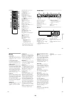
Front panel
114
Front panel display
117
H
Handling discs
110
HDMI
16
,
119
“HDMI Resolution”
96
I
i.LINK
90
,
113
INPUT
48
,
76
,
91
Interlace format
119
J
JPEG image files
42
L
“Language”
102
Language abbreviation
120
LINE 1 IN
13
LINE 2 IN
27
127
“Line Audio Input”
51
,
55
,
100
M
MENU
35
Menu
Top menu
35
“Mode for SET button”
102
“Modify”
64
“Move”
65
MP3 audio tracks
41
N
NEXT
36
,
71
Number buttons
21
,
40
O
One Touch Dubbing
93
On-screen display
OPTIONS menu
11
Setup Display
94
Sub-menu
11
System Menu
10
OPTIONS
11
Options settings
102
Original
39
,
119
ORIGINAL/PLAYLIST
39
,
57
“OSD” language
24
,
102
P
“Parental”
103
Parental Control
38
Parts and controls
114
PAUSE
37
,
48
,
71
,
76
PBC
38
“Picture Control”
97
PLAY
35
,
69
Playable discs
33
Playback
35
,
69
JPEG image files
42
MP3 audio tracks
41
Resume Play
38
Slow-motion play
37
,
71
Playlist
39
,
61
,
119
Power cord
20
PREV
36
,
71
Program Dubbing
86
“Progressive”
97
Progressive format
119
“Protect”
58
Q
Quick Timer
48
,
76
R
Rear panel
117
REC
48
,
76
REC MODE
48
,
76
Recording
46
,
75
recordable discs
30
recording format
30
recording mode
46
tape speed
75
Recording mode
46
,
75
Recording time
46
,
49
Region code
34
Remaining time
44
,
77
Remote
20
,
115
REPLAY
36
,
71
Resetting
104
Resume Play
38
Rotate
42
S
Safety tab
75
Satellite receiver
13
Satellite receiver brand code
124
“Scan Audio”
38
,
99
“Scene Dubbing”
87
Searching
for “Chapter”
40
for “Title”
40
for “Track”
40
Time Search
40
Set top box control
12
,
24
,
101
Set top box controller
12
,
26
Settings
94
Setup Display
94
“Simple Dubbing”
86
Slide show
42
,
43
SP mode
76
STOP
35
,
48
,
69
,
76
Sub-menu
11
SUBTITLE
36
“Subtitle”
102
“Surround”
99
SYNCHRO REC
52
,
80
“Synchro Recording”
52
,
80
,
101
System Menu
10
T
“Tape Length”
101
Tape speed
75
TIME/TEXT
45
,
73
TIMER
50
,
78
Timer List
53
,
81
Timer recording
49
,
78
change or cancel
53
,
81
Title
119
“Title Dubbing”
87
“Title Erase”
58
,
63
TITLE LIST
39
,
57
Title List
39
“Title Name”
58
,
63
TOP MENU
35
Track
119
TRACKING
70
Tracking adjustment
70
Troubleshooting
105
“TV Type”
96
U
“Unfinalize”
89
Unrecordable pictures
47
V
“VCR Function”
101
“Video (HDMI)”
96
VIDEO CD
33
Video mode
30
Video settings
96
VR mode
30
Z
Zoom
42
Содержание RDR VX555 - DVDr/ VCR Combo
Страница 62: ...2 22 2 22E MEMO ...
Страница 64: ...3 4E MEMO ...
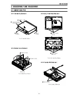
Страница 66: ...4 1 DVD Main PCB 4 4 4 3 COMPONENT SIDE ...
Страница 67: ...4 6 4 5 CONDUCTOR SIDE ...
Страница 68: ...4 8 4 7 4 2 VCR Main PCB COMPONENT SIDE ...
Страница 69: ...4 10 4 9 CONDUCTOR SIDE ...
Страница 70: ...4 12 4 11 4 3 Function PCB COMPONENT SIDE COMPONENT SIDE ...
Страница 71: ...4 14 4 13 4 4 Front Jack PCB COMPONENT SIDE CONDUCTOR SIDE ...
Страница 72: ...4 16E 4 15 4 5 DV Jack PCB COMPONENT SIDE COMPONENT SIDE ...
Страница 74: ...5 4 5 3 5 1 S M P S VCR Main PCB ...
Страница 75: ...5 6 5 5 5 2 Power VCR Main PCB ...
Страница 76: ...5 8 5 7 5 3 Logic VCR Main PCB ...
Страница 77: ...5 10 5 9 5 4 A V VCR Main PCB ...
Страница 78: ...5 12 5 11 5 5 Hi Fi VCR Main PCB ...
Страница 79: ...5 14 5 13 5 6 MPEG Decoder DVD Main PCB ...
Страница 80: ...5 16 5 15 5 7 A V Decoder DVD Main PCB ...
Страница 81: ...5 18 5 17 5 8 In Out DVD Main PCB ...
Страница 82: ...5 20 5 19 5 9 DV HDMI DVD Main PCB ...
Страница 83: ...5 22 5 21 5 10 Front Timer Front Jack PCB DV Jack DV Jack PCB ...
Страница 84: ...5 24E 5 23 5 11 Function Function PCB ...
Страница 127: ...MEMO ...


