


1-23
95
Set
tin
g
s a
nd
Adj
us
tm
en
ts
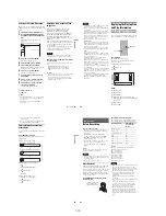
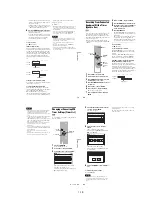
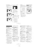
Some items display a dialog box that requires
additional settings.
Example: When “Parental” in “Options”
setup is selected.
5
Select an option, and press ENTER.
The currently selected option is displayed
next to the setup item.
Example: When “16:9” is set.
To return to the previous display
Press
O
RETURN.
To turn off the display
Press SYSTEM MENU.
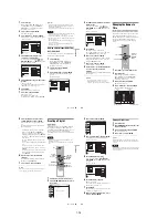
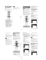
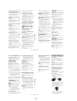
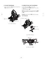
Clock Setting (Clock Set)
The “Clock Set” setup allows you to make clock
settings for the recorder.
1
Press SYSTEM MENU while the recorder is
in stop mode.
2
Select “Setup,” and press ENTER.
3
Select “Clock Set,” and press ENTER.
The clock setting display appears.
4
Press
M
/
m
to set the month, and press
,
.
Set the day, year, hour, minutes, and AM/PM
in sequence. Press
<
/
,
to select the item to
be set, then press
M
/
m
to set the item. The day
of the week is set automatically.
5
Press ENTER to start the clock.
10:10 AM
Create the password.
Create the password
Setup
Disc Setting
Edit
Title List
Timer
Dubbing
Video
10:10 AM
TV Type
HDMI Resolution
Video (HDMI)
Black Level
Picture Control
Progressive
: 16:9
: Auto
: Y Cb Cr
: On
: Standard
: Off
Setup
Disc Setting
Edit
Title List
Timer
Dubbing
2007
Mon
01
01
10 : 10
AM
10:10 AM
Clock Set
Set the time and date manually.
Hour Min AM/PM
Month Day
Year
Setup
Disc Setting
Edit
Title List
Timer
Dubbing
96
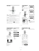
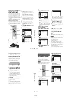
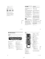
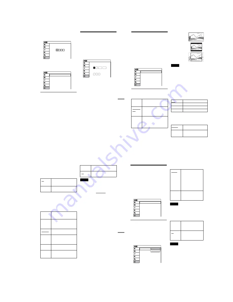
Video Settings (Video)
The “Video” setup allows you to adjust items
related to the image, such as size and color.
Choose the settings according to the type of TV,
tuner, or decoder connected to the recorder.
1
Press SYSTEM MENU while the recorder is
in stop mode.
2
Select “Setup,” and press ENTER.
3
Select “Video,” and press ENTER.
The “Video” setup appears with the following
options. The default settings are underlined.
TV Type
Selects the aspect ratio of the connected TV (4:3
standard or wide).
Note
Depending on the disc, “4:3 Letter Box” may be selected
automatically instead of “4:3 Pan Scan” or vice versa.
HDMI Resolution
Selects the type of video signals output from the
HDMI OUT jack. When you select “Auto”
(default), the recorder outputs video signals of the
highest resolution acceptable for your TV. If the
picture is not clear, unnatural or not to your
satisfaction, try another option that suits the disc
and your TV/projector, etc. For details, refer also
to the instruction manual supplied with the TV/
projector, etc.
The setting is effective only when you connect a
HDMI equipped TV to the HDMI OUT jack.
Video (HDMI)
Selects the type of output from the HDMI OUT
jack.
The setting is effective only when you connect a
HDMI equipped TV to the HDMI OUT jack.
16:9
Select this when connecting to a
wide-screen TV or TV with a
wide mode function.
4:3 Letter
Box
Select this when connecting to a
4:3 screen TV. Displays a wide
picture with bands on the upper
and lower portions of the screen.
4:3 Pan
Scan
Select this when connecting to a
4:3 screen TV. Automatically
displays a wide picture on the
entire screen and cuts off the
portions that do not fit.
Video
10:10 AM
TV Type
HDMI Resolution
Video (HDMI)
Black Level
Picture Control
Progressive
: 4:3 Letter Box
: Auto
: Y Cb Cr
: On
: Standard
: Off
Setup
Disc Setting
Edit
Title List
Timer
Dubbing
Auto
Normally, select this.
1920×1080i
Sends 1920×1080i video signals.
1280×720P
Sends 1280×720p video signals.
720×480P
Sends 720×480p video signals.
Y Cb Cr
Normally, select this when
connecting to an HDMI device.
RGB
Gives brighter colors and deeper
black. Select this if colors are
weak.
16:9
4:3 Letter Box
4:3 Pan Scan
97
Set
tin
g
s a
nd
Adj
us
tm
en
ts
Black Level
Selects the black level (setup level) for the video
signals output from the LINE OUT jacks
(page 15).
This setting is not effective when the recorder
outputs progressive signals.
Picture Control
Selects the picture control for the video signals
output from the LINE OUT jacks (page 15).
You can adjust the video signal of DVD or
VIDEO CD (with PBC function off) from the
recorder to obtain the picture quality you want.
Select the setting that best suits the program you
are watching.
z
Hint
When you watch a movie, “Cinema 1” or “Cinema 2” is
recommended.
Progressive
If your TV accepts progressive (480p) format
signals, you will enjoy accurate color reproduction
and high quality image.
Connect your TV to the COMPONENT VIDEO
OUT jacks (page 17).
Notes
• If you select progressive signals when you connect the
recorder to a TV that cannot accept the signal in
progressive format, the image quality will deteriorate.
In this case, set “Progressive” to “Off.” Or, press DVD
in stop mode to operate the DVD recorder, and then
hold down
X
PAUSE on the recorder for five seconds
or more.
• When you connect your TV using an HDMI cable, the
“Progressive” setting is set to “On.”
On
Raises the standard black level.
Select this when the picture
appears too dark.
Off
Sets the black level of the output
signal to the standard level.
Dynamic 1
Produces a bold dynamic picture
by increasing the picture contrast
and the color intensity.
Dynamic 2
Produces a more dynamic picture
than “Dynamic 1” by further
increasing the picture contrast
and the color intensity.
Standard
Displays a standard picture
(function turned off).
Cinema 1
White colors become brighter
and black colors become richer,
and the color contrast is
increased.
Cinema 2
Enhances details in dark areas by
increasing the black level.
Personal
Adjusts “Contrast,” “Brightness,”
“Color,” and “Hue” using
M
/
m
/
<
/
,
.
On
Sets the recorder to output
progressive signals.
Off
Outputs video signals in interlace
format.
98
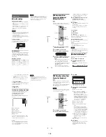
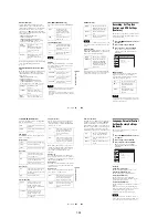
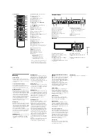
Audio Settings (Audio)
The “Audio” setup allows you to adjust the sound
according to the playback and connection
conditions.
1
Press SYSTEM MENU while the recorder is
in stop mode.
2
Select “Setup,” and press ENTER.
3
Select “Audio,” and press ENTER.
The “Audio” setup appears with the following
options. The default settings are underlined.
Digital Out
The following setup items switch the method of
outputting audio signals when you connect a
component such as an amplifier (receiver) to the
DIGITAL AUDIO OUT (OPTICAL or
COAXIAL)/HDMI OUT jack.
For connection details, see “Connecting to Your
AV Amplifier (Receiver)” on page 18.
Press ENTER, and select “Dolby Digital” or
“DTS.”
If you connect a component that does not accept
the selected audio signal, a loud noise (or no
sound) will come out from the speakers, and may
affect your ears or cause speaker damage.
◆
Dolby Digital (DVDs only)
Selects the type of Dolby Digital signal.
Note
If the HDMI OUT jack is connected to equipment not
compatible with Dolby Digital signals, D-PCM signals
will be automatically output, even when “Dolby Digital”
is selected.
◆
DTS (DVD VIDEOs only)
Selects whether or not to output DTS signals.
Note
If the HDMI OUT jack is connected to equipment not
compatible with DTS signals, no signal will be output,
regardless of the “DTS” setting.
Audio
10:10 AM
Digital Out
Downmix
Audio DRC
Audio (HDMI)
Scan Audio
Surround
DV/D8 Audio Input
Line Audio Input
: Dolby Surround
: Standard
: Auto
: On
: Off
: Stereo 1
: Stereo
Setup
Disc Setting
Edit
Title List
Timer
Dubbing
10:10 AM
Dolby Digital
DTS
Digital Out
: 4:3 Letter Box
On
Setup
Disc Setting
Edit
Title List
Timer
Dubbing
D-PCM
Dolby Digital
D-PCM
Select this when the recorder
is connected to an audio
component lacking a built-in
Dolby Digital decoder. You
can select whether the
signals conform to Dolby
Surround or not by making
adjustments to the
“Downmix” item in “Audio”
setup (page 99).
Dolby
Digital
Select this when the recorder
is connected to an audio
component with a built-in
Dolby Digital decoder.
On
Select this when the recorder
is connected to an audio
component with a built-in
DTS decoder.
Off
Select this when the recorder
is connected to an audio
component without a built-in
DTS decoder.
Содержание RDR VX555 - DVDr/ VCR Combo
Страница 62: ...2 22 2 22E MEMO ...
Страница 64: ...3 4E MEMO ...
Страница 66: ...4 1 DVD Main PCB 4 4 4 3 COMPONENT SIDE ...
Страница 67: ...4 6 4 5 CONDUCTOR SIDE ...
Страница 68: ...4 8 4 7 4 2 VCR Main PCB COMPONENT SIDE ...
Страница 69: ...4 10 4 9 CONDUCTOR SIDE ...
Страница 70: ...4 12 4 11 4 3 Function PCB COMPONENT SIDE COMPONENT SIDE ...
Страница 71: ...4 14 4 13 4 4 Front Jack PCB COMPONENT SIDE CONDUCTOR SIDE ...
Страница 72: ...4 16E 4 15 4 5 DV Jack PCB COMPONENT SIDE COMPONENT SIDE ...
Страница 74: ...5 4 5 3 5 1 S M P S VCR Main PCB ...
Страница 75: ...5 6 5 5 5 2 Power VCR Main PCB ...
Страница 76: ...5 8 5 7 5 3 Logic VCR Main PCB ...
Страница 77: ...5 10 5 9 5 4 A V VCR Main PCB ...
Страница 78: ...5 12 5 11 5 5 Hi Fi VCR Main PCB ...
Страница 79: ...5 14 5 13 5 6 MPEG Decoder DVD Main PCB ...
Страница 80: ...5 16 5 15 5 7 A V Decoder DVD Main PCB ...
Страница 81: ...5 18 5 17 5 8 In Out DVD Main PCB ...
Страница 82: ...5 20 5 19 5 9 DV HDMI DVD Main PCB ...
Страница 83: ...5 22 5 21 5 10 Front Timer Front Jack PCB DV Jack DV Jack PCB ...
Страница 84: ...5 24E 5 23 5 11 Function Function PCB ...
Страница 127: ...MEMO ...


