


1-4
19
Ho
o
kup
s a
nd Set
tings
A
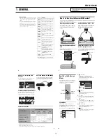
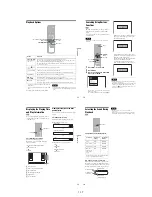
Connecting to audio L/R jacks
This connection uses a stereo amplifier’s
(receiver’s) two front speakers for sound.
You can enjoy the surround function that creates
virtual speakers from two stereo speakers. Select
“Surround1,” “Surround2,” or “Surround3” in
“Surround” of “Audio” setup (page 99).
Surround 1
Surround 2
Surround 3
Note
Make sure that your listening position is between and at
an equal distance from your speakers, and that the
speakers are located in similar surroundings.
B
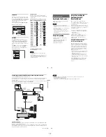
Connecting to a digital audio input jack
Use this connection if your AV amplifier
(receiver) has a Dolby
*1
Digital or DTS
*2
decoder
and a digital input jack. You can enjoy the
surround effect of Dolby Digital (5.1ch) or DTS
(5.1ch).
*1
Manufactured under license from Dolby Laboratories.
“Dolby” and the double-D symbol are trademarks of
Dolby Laboratories.
*2
“DTS” and “DTS Digital Out” are trademarks of DTS,
Inc.
z
Hints
• For correct speaker location, see the operating
instructions supplied with the connected components.
• During VHS playback, the DIGITAL AUDIO OUT
jacks can also output digital audio signals.
Notes
• During DVD recording, the DIGITAL AUDIO OUT
jacks or HDMI OUT jack output DVD audio signals
only. You cannot hear VHS sound by pressing VIDEO.
• After you have completed the connection, make the
appropriate settings under “Audio Connection Setup”
in Easy Setup (page 23). Otherwise, no sound or a loud
noise will come from your speakers.
• With a coaxial or optical digital connection, you cannot
use the virtual surround effects of this recorder.
• When outputting from the DIGITAL AUDIO OUT
jacks, you cannot switch the bilingual sounds on a
DVD-RW (VR mode) or DVD-R (VR mode) by
pressing AUDIO.
• When you connect the recorder to an AV amplifier
(receiver) using an HDMI cord, you will need to do one
of the following:
– Connect the AV amplifier (receiver) to the TV with
an HDMI cord.
– Connect the recorder to the TV with a video cord
other than HDMI cord (component video cord,
S VIDEO cord, or audio/video cord).
Virtual speaker
20
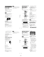
Step 5: Connecting the
Power Cord
Plug the recorder and TV power cords into an AC
outlet. After you connect the power cord,
you
must wait for a short while before
operating the recorder
.
You can operate the
recorder only after the front panel display lights up
and the recorder enters standby mode.
If you connect additional equipment to this
recorder (page 27), be sure to connect the power
cord only after all connections are complete.
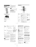
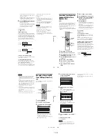
Step 6: Preparing the
Remote
You can control the recorder using the supplied
remote.
Insert two size AA (R6) batteries by matching the
3
and
#
ends on the batteries to the markings
inside the battery compartment. Be sure to close
the battery cover properly. When using the
remote, point it at the remote sensor
on the
recorder.
Notes
• If the supplied remote interferes your other Sony DVD
recorder or player, change the command mode number
for this recorder (page 22).
• Use the batteries correctly to avoid possible leakage
and corrosion. Do not touch the liquid with bare hands
should leakage occur. Observe the following:
– Do not use a new battery with an old battery, or
batteries of different manufacturers.
– Do not attempt to recharge the batteries.
– If you do not intend to use the remote for an extended
period of time, remove the batteries.
– If battery leakage occurs, wipe out any liquid inside
the battery compartment, and insert new batteries.
• Do not expose the remote sensor (marked
on the
front panel) to strong light, such as direct sunlight or
lighting apparatus. The recorder may not respond to the
remote.
• With normal use, the batteries should last about three to
six months.
• Do not leave the remote in an extremely hot or humid
place.
• Do not drop any foreign object into the remote casing,
particularly when replacing the batteries.
Y
L
PB
R
PR
AUDIO OUT COMPONENT
VIDEO OUT
DIGITAL AUDIO OUT
OPTICAL COAXIAL
HDMI OUT
SETTOP
BOX
CONTROL
to AC outlet
<
21
Ho
o
kup
s
an
d
S
e
tt
in
g
s
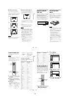
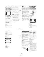
Controlling TVs with the remote
You can adjust the remote control’s signal to
control your TV.
Notes
• Depending on the TV, some or all of the buttons below
may not work for the TV.
• If you enter a new code number, the code number
previously entered will be erased.
• When you replace the batteries of the remote, the code
number may be reset to the default setting. Set the
appropriate code number again.
1
Hold down TV
"/1
located at the bottom of
the remote.
Do not press
"/1
at the top of the remote.
2
With TV
"/1
pressed down, enter your
TV’s manufacturer code (see below) using
the number buttons.
3
Release TV
"/1
.
The following buttons are for TV.
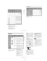
Code numbers of controllable TVs
If more than one code number is listed, try
entering them one at a time until you find the one
that works with your TV.
Press
To
TV
"/1
Turn your TV on or off
TV VOL +/–
Adjust the volume of
your TV
TV CH +/–
Select the channel on
your TV
1
1
2
2
3
3
4
4
5
5
6
6
7
7
8
8
0
0
9
9
TV
"/1
TV VOL +/–
TV INPUT
TV CH +/–
TV DIGITAL/
ANALOG
Number
buttons
TV INPUT
Switch your TV’s input
source
TV DIGITAL/
ANALOG
Select the broadcast on a
Sony TV that can switch
between digital and
analog
Manufacturer
Code number
Sony
01 (default)
Akai
04
AOC
04
Centurion
12
Coronado
03
Curtis-Mathes
12, 14
Daewoo
04, 22
Daytron
03, 12
Fisher
11
General Electric
04, 06, 10
Hitachi
02, 03, 04
J.C.Penney
04, 10, 12
JVC
09
KMC
03
LG/Gold Star
03, 04, 17
Magnavox
03, 04, 08, 12, 21
Marantz
04, 13
MGA/Mitsubishi
04, 12, 13, 17
NEC
04, 12
Panasonic
06, 19
Philco
02, 03, 04, 08
Philips
08, 21
Pioneer
06, 16
Portland
03
Proscan
10
Quasar
06, 18
Radio Shack
05, 10, 14
RCA
04, 10
,
continued
22
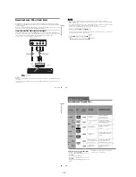
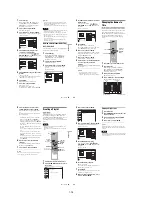
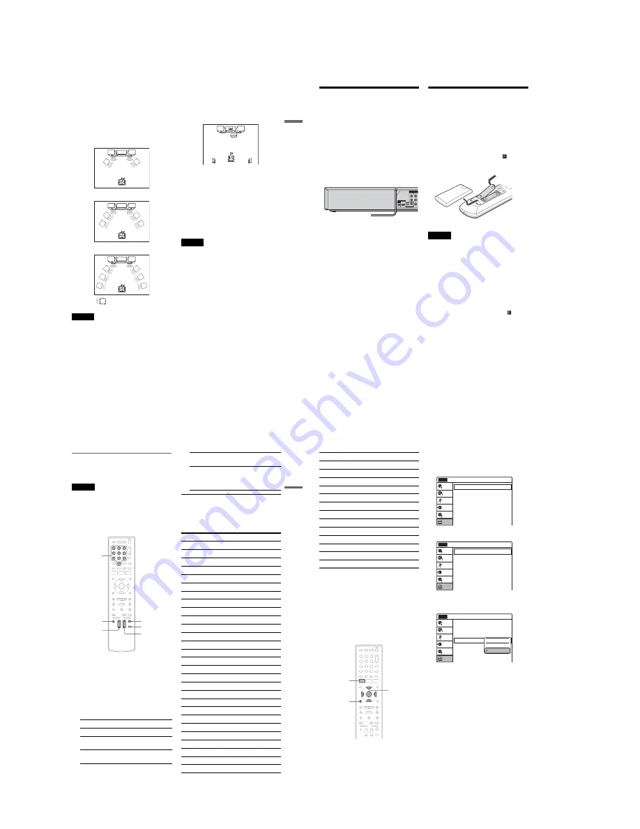
If you have a Sony DVD player or
more than one Sony DVD recorder
If the supplied remote interferes with your other
Sony DVD recorder or player, set the command
mode number for this recorder and the supplied
remote to one that differs from the other Sony
DVD recorder or player, after you have completed
“Step 7: Easy Setup.”
The default command mode setting for this
recorder and the supplied remote is DVD 3.
1
Check that Easy Setup (page 23) has been
finished. If Easy Setup has not been
finished, first perform Easy Setup.
2
Press SYSTEM MENU.
The System Menu appears.
3
Select “Setup,” and press ENTER.
4
Select “Options,” and press ENTER.
5
Select “Command Mode,” and press
ENTER.
6
Select a command mode (“DVD 1,” “DVD
2,” or “DVD 3”), and press ENTER.
Sampo
12
Samsung
03, 04, 12, 20
Sanyo
11, 14
Scott
12
Sears
07, 10, 11
Sharp
03, 05, 18
Sylvania
08, 12
Teknika
03, 08, 14
Toshiba
07, 18
Wards
03, 04, 12
Yorx
12
Zenith
14, 15
Manufacturer
Code number
1
1
2
2
3
3
4
4
5
5
6
6
7
7
8
8
0
0
9
9
SYSTEM
MENU
M
/
m
/
<
/
,
,
ENTER
O
RETURN
10:10 AM
Clock Set
Video
Audio
Features
Options
Easy Setup
Setup
Disc Setting
Edit
Title List
Timer
Dubbing
Setup
No Disc
Options
Language
Parental
Front Display
Command Mode
Factory Setting
: Auto
: DVD 3
10:10 AM
Setup
Disc Setting
Edit
Title List
Timer
Dubbing
No Disc
Options
Language
Parental
Front Display
Command Mode
Factory Setting
: Auto
: DVD1 No
10:10 AM
Setup
Disc Setting
Edit
Title List
Timer
Dubbing
No Disc
DVD 1
DVD 2
DVD 3
Содержание RDR VX555 - DVDr/ VCR Combo
Страница 62: ...2 22 2 22E MEMO ...
Страница 64: ...3 4E MEMO ...
Страница 66: ...4 1 DVD Main PCB 4 4 4 3 COMPONENT SIDE ...
Страница 67: ...4 6 4 5 CONDUCTOR SIDE ...
Страница 68: ...4 8 4 7 4 2 VCR Main PCB COMPONENT SIDE ...
Страница 69: ...4 10 4 9 CONDUCTOR SIDE ...
Страница 70: ...4 12 4 11 4 3 Function PCB COMPONENT SIDE COMPONENT SIDE ...
Страница 71: ...4 14 4 13 4 4 Front Jack PCB COMPONENT SIDE CONDUCTOR SIDE ...
Страница 72: ...4 16E 4 15 4 5 DV Jack PCB COMPONENT SIDE COMPONENT SIDE ...
Страница 74: ...5 4 5 3 5 1 S M P S VCR Main PCB ...
Страница 75: ...5 6 5 5 5 2 Power VCR Main PCB ...
Страница 76: ...5 8 5 7 5 3 Logic VCR Main PCB ...
Страница 77: ...5 10 5 9 5 4 A V VCR Main PCB ...
Страница 78: ...5 12 5 11 5 5 Hi Fi VCR Main PCB ...
Страница 79: ...5 14 5 13 5 6 MPEG Decoder DVD Main PCB ...
Страница 80: ...5 16 5 15 5 7 A V Decoder DVD Main PCB ...
Страница 81: ...5 18 5 17 5 8 In Out DVD Main PCB ...
Страница 82: ...5 20 5 19 5 9 DV HDMI DVD Main PCB ...
Страница 83: ...5 22 5 21 5 10 Front Timer Front Jack PCB DV Jack DV Jack PCB ...
Страница 84: ...5 24E 5 23 5 11 Function Function PCB ...
Страница 127: ...MEMO ...


