


1-3
15
Ho
ok
up
s a
nd Set
tings
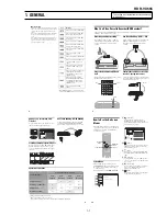
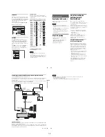
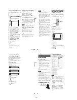
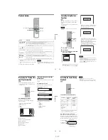
Step 3: Connecting to Your TV
Connect the supplied audio/video cord to the LINE OUT (VIDEO/AUDIO L/R) jacks of the recorder.
To enjoy higher quality images, connect an S video cord (not supplied) instead of the yellow (video) plug.
When using this connection, be sure to connect the audio cord to the LINE OUT (AUDIO L/R) jacks.
When playing “wide screen” images
Some recorded images may not fit your TV screen. To change the picture size, see page 96.
Notes
• Do not connect to the S VIDEO OUT and yellow LINE OUT (VIDEO) jacks at the same time.
• During DVD recording, you cannot watch VHS pictures by pressing VIDEO, as the S VIDEO OUT jack will output
DVD video signals only.
• Do not connect your TV’s audio output jacks to the LINE IN (AUDIO L/R) jacks at the same time. This will cause
unwanted noise to come from your TV’s speakers.
L
R
VIDEO
AUDIO
LINE OUT
VIDEO
Y
L
PB
R
PR
AUDIO
LINE 1 IN
AUDIO OUT
S VIDEO OUT
COMPONENT
VIDEO OUT
DIGITAL AUDIO OUT
OPTICAL COAXIAL
HDMI OUT
SETTOP
BOX
CONTROL
L
R
VIDEO
AUDIO
LINE OUT
VIDEO
AUDIO
LINE 1 IN
S VIDEO OUT
AUDIO
INPUT
R
L
VIDEO
INPUT
S VIDEO
: Signal flow
S video cord
(not supplied)
TV or projector
(red)
(white) (yellow)
Audio/video cord
(supplied)
(red)
(white)
(yellow)
to S VIDEO OUT
VCR-DVD recorder
to LINE OUT
(VIDEO/AUDIO L/R)
,
continued
16
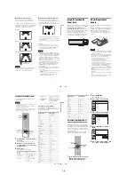
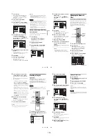
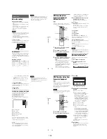
If your TV has an HDMI input jack
Connect the HDMI* OUT jack using a certified HDMI cord (not supplied). You will enjoy high quality
picture and sound. The HDMI indicator lights up on the front panel when the recorder outputs signals
through the HDMI OUT jack.
Be sure to turn off the recorder before connecting an HDMI cord.
* This DVD recorder incorporates High-Definition Multimedia Interface (HDMI™) technology.
HDMI, the HDMI logo and High-Definition Multimedia Interface are trademarks or registered trademarks of HDMI
Licensing LLC.
Notes
• You cannot connect the HDMI OUT jack to DVI jacks that are not HDCP compliant (e.g., DVI jacks on PC displays).
• During DVD recording, you cannot watch VHS pictures by pressing VIDEO, as the HDMI OUT jack will output
DVD video signals only.
L
R
VIDEO
AUDIO
LINE OUT
VIDEO
Y
L
PB
R
PR
AUDIO
LINE 1 IN
AUDIO OUT
S VIDEO OUT
COMPONENT
VIDEO OUT
DIGITAL AUDIO OUT
OPTICAL COAXIAL
HDMI OUT
SETTOP
BOX
CONTROL
HDMI IN
HDMI OUT
TV or
projector
HDMI cord (not supplied)
to HDMI OUT
: Signal flow
VCR-DVD recorder
to HDMI input
17
Ho
o
kup
s
an
d
S
e
tt
in
g
s
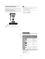
If your TV has component video input jacks
Connect the COMPONENT VIDEO OUT jacks using a component video cord (not supplied) or three
video cords (not supplied) of the same kind and length. You will enjoy accurate color reproduction and
high quality images.
If your TV accepts progressive 480p format signals, you must use this connection and then set
“Progressive” of “Video” to “On” in the “Setup” display (page 97).
When using this connection, be sure to connect the audio cord to the LINE OUT (AUDIO L/R) jacks.
Note
During DVD recording, you cannot watch VHS pictures by pressing VIDEO, as the COMPONENT VIDEO OUT jacks
will output DVD video signals only.
L
R
VIDEO
AUDIO
LINE OUT
VIDEO
Y
L
PB
R
PR
AUDIO
LINE 1 IN
AUDIO OUT
S VIDEO OUT
COMPONENT
VIDEO OUT
DIGITAL AUDIO OUT
OPTICAL COAXIAL
HDMI OUT
SETTOP
BOX
CONTROL
Y
P
B
P
R
COMPONENT
VIDEO OUT
COMPONENT VIDEO IN
P
B
P
R
Y
AUDIO
L
R
INPUT
L
R
VIDEO
AUDIO
LINE OUT
: Signal flow
TV or projector
(red)
(white)
(green)
Component video cord
(not supplied)
(red)
(blue)
(red)
(green)
(blue)
to COMPONENT
VIDEO OUT
Audio/video cord
(supplied)
(white)
(red)
to LINE OUT
(AUDIO L/R)
VCR-DVD recorder
18
Step 4: Connecting to Your AV Amplifier (Receiver)
Select one of the following patterns
A
or
B
, according to the input jack on your AV amplifier (receiver).
This will enable you to listen to DVD audio tracks through your AV amplifier (receiver).
L
R
VIDEO
AUDIO
LINE OUT
VIDEO
Y
L
PB
R
PR
AUDIO
LINE 1 IN
AUDIO OUT
S VIDEO OUT
COMPONENT
VIDEO OUT
DIGITAL AUDIO OUT
OPTICAL COAXIAL
HDMI OUT
SETTOP
BOX
CONTROL
AUDIO
INPUT
L
R
L
R
AUDIO OUT
B
A
DIGITAL AUDIO OUT
OPTICAL COAXIAL
HDMI OUT
: Signal flow
AV amplifier (receiver)
(red)
(white)
Audio cord
(not supplied)
(white)
(red)
VCR-DVD recorder
to AUDIO OUT (L/R)
to DIGITAL AUDIO OUT
(COAXIAL or OPTICAL)
Optical digital cord
(not supplied)
Coaxial digital cord
(not supplied)
[Speakers]
Rear (L)
Front (L)
Center
to coaxial or
optical digital
input
[Speakers]
Rear (R)
Front (R)
Subwoofer
or
AV amplifier (receiver)
with a decoder
HDMI cord
(not supplied)
or
to HDMI OUT
to HDMI input
Содержание RDR VX555 - DVDr/ VCR Combo
Страница 62: ...2 22 2 22E MEMO ...
Страница 64: ...3 4E MEMO ...
Страница 66: ...4 1 DVD Main PCB 4 4 4 3 COMPONENT SIDE ...
Страница 67: ...4 6 4 5 CONDUCTOR SIDE ...
Страница 68: ...4 8 4 7 4 2 VCR Main PCB COMPONENT SIDE ...
Страница 69: ...4 10 4 9 CONDUCTOR SIDE ...
Страница 70: ...4 12 4 11 4 3 Function PCB COMPONENT SIDE COMPONENT SIDE ...
Страница 71: ...4 14 4 13 4 4 Front Jack PCB COMPONENT SIDE CONDUCTOR SIDE ...
Страница 72: ...4 16E 4 15 4 5 DV Jack PCB COMPONENT SIDE COMPONENT SIDE ...
Страница 74: ...5 4 5 3 5 1 S M P S VCR Main PCB ...
Страница 75: ...5 6 5 5 5 2 Power VCR Main PCB ...
Страница 76: ...5 8 5 7 5 3 Logic VCR Main PCB ...
Страница 77: ...5 10 5 9 5 4 A V VCR Main PCB ...
Страница 78: ...5 12 5 11 5 5 Hi Fi VCR Main PCB ...
Страница 79: ...5 14 5 13 5 6 MPEG Decoder DVD Main PCB ...
Страница 80: ...5 16 5 15 5 7 A V Decoder DVD Main PCB ...
Страница 81: ...5 18 5 17 5 8 In Out DVD Main PCB ...
Страница 82: ...5 20 5 19 5 9 DV HDMI DVD Main PCB ...
Страница 83: ...5 22 5 21 5 10 Front Timer Front Jack PCB DV Jack DV Jack PCB ...
Страница 84: ...5 24E 5 23 5 11 Function Function PCB ...
Страница 127: ...MEMO ...


