


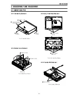


1-27
111
Add
iti
o
n
a
l I
n
fo
rm
at
io
n
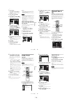
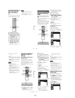
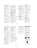
– A disc that has a non-standard shape (e.g.,
card, heart).
– A disc with a label or sticker on it.
– A disc that has cellophane tape or sticker
adhesive on it.
Symptoms caused by contaminated video
heads
When the video heads are dirty, the picture is
distorted or the tape cannot be played.
Clean the video heads using a Sony video head
cleaning cassette. If a Sony cleaning cassette is not
available in your area, have the heads cleaned at
your nearest Sony dealer (a standard service fee
will be charged). Do not use a commercially
available liquid type cleaning cassette, as it may
damage the video heads.
initial
contamination
terminal
,
continued
113
Addi
tion
al
I
n
fo
rm
at
io
n
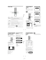
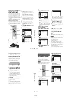
About i.LINK
The DV IN jack on this recorder is an i.LINK-
compliant DV IN jack. This section describes the
i.LINK standard and its features.
What is i.LINK?
i.LINK is a digital serial interface for handling
digital video, digital audio and other data in two
directions between equipment having the i.LINK
jack, and for controlling other equipment.
i.LINK-compatible pieces of equipment can be
connected by a single i.LINK cable. Possible
applications are operations and data transactions
with various digital AV equipment. When two or
more i.LINK-compatible equipment are
connected to this recorder in a daisy chain,
operations and data transactions are possible with
not only the equipment that this recorder is
connected to but also with other devices via the
directly connected equipment.
Note, however, that the method of operation
sometimes varies according to the characteristics
and specifications of the equipment to be
connected, and that operations and data
transactions are sometimes not possible on some
connected equipment.
Note
Normally, only one piece of equipment can be connected
to this recorder by the i.LINK cable (DV connecting
cable). When connecting this recorder to i.LINK-
compatible equipment having two or more i.LINK jacks
(DV jacks), see the instruction manual of the equipment
to be connected.
About the name “i.LINK”
i.LINK is a more familiar term for IEEE 1394 data
transport bus proposed by SONY, and is a
trademark approved by many corporations.
IEEE 1394 is an international standard
standardized by the Institute of Electrical and
Electronics Engineers.
i.LINK baud rate
i.LINK’s maximum baud rate varies according to
the equipment. Three maximum baud rates are
defined:
S100 (approx. 100 Mbps*)
S200 (approx. 200 Mbps)
S400 (approx. 400 Mbps)
The baud rate is listed under “Specifications” in
the instruction manual of each equipment. It is
also indicated near the i.LINK jack on some
equipment.
The maximum baud rate of equipment on which it
is not indicated such as this unit is “S100.”
When units are connected to equipment having a
different maximum baud rate, the baud rate
sometimes differs from the indicated baud rate.
* What is Mbps?
Mbps stands for megabits per second, or the amount of
data that can be sent or received in one second. For
example, a baud rate of 100 Mbps means that 100
megabits of data can be sent in one second.
i.LINK functions on this recorder
For details on how to dub when this recorder is
connected to other video equipment having DV
jacks, see page 90.
The DV jack on this recorder can only input DVC-
SD signals. It cannot output signals. The DV jack
will not accept MICROMV signals from
equipment such as a MICROMV digital video
camera with an i.LINK jack.
For further precautions, see the notes on page 90.
For details on precautions when connecting this
recorder, also see the instruction manuals for the
equipment to be connected.
Required i.LINK cable
Use the Sony i.LINK 4-pin-to-4-pin cable (during
DV/D8 dubbing).
i.LINK and
are
trademarks.
114
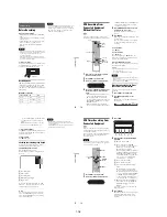
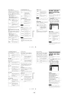
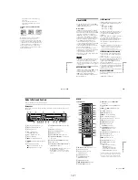
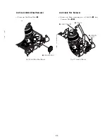
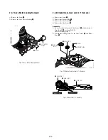
Guide to Parts and Controls
For more information, see the pages in parentheses.
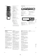
Front panel
Buttons on the recorder have the same function as the buttons on the remote if they have the same or
similar names.
A
A
(open/close) button (35, 47, 91)
B
"/1
(on/standby) switch (23)
C
Disc tray (35, 47, 91)
D
DVD
t
button (85)
T
VIDEO button (84)
E
Tape compartment (69, 76)
F
A
(eject) button (69)
G
z
REC (record) button (47, 76)
H
m
/
M
(rewind/fast-forward) buttons
(37)
I
H
(play) button (35, 69)
X
(pause) button (36, 47, 71, 76)
x
(stop) button (35, 47, 69, 76)
J
SELECT DVD/VIDEO buttons (35, 47, 69,
76)
K
(remote sensor) (20)
L
Front panel display (45, 73)
M
HDMI indicator (16)
N
SYNCHRO REC indicator (51, 80)
O
CHANNEL/TR/– buttons*
1
*
2
(47, 70, 76)
P
ONE-TOUCH DUBBING button (93)
Q
DV IN jack (90)
R
LINE 2 IN (S VIDEO/VIDEO/AUDIO L
(MONO)/R) jacks (27)
*1
The CHANNEL/TR button has a tactile
dot. Use the tactile dot as a reference.
*2
The C/– buttons are used for channel
selection when the set top box control is turned on
(page 12).
Open the
cover
115
Addi
tion
al
I
n
fo
rm
at
io
n
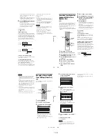
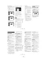
Remote
For DVD functions
A
Z
OPEN/CLOSE button (35, 47, 91)
B
DVD button (35, 47)
C
Number buttons*
1
(21, 36)
SET button (102)
D
ANGLE button (36)
E
TOP MENU button (35)
MENU button (35)
F
DISPLAY button (44)
G
M
/
m
/
<
/
,
/ENTER button (23)
H
O
RETURN button (23)
I
.
PREV (previous)/
>
NEXT
buttons (36)
J
REPLAY/
ADVANCE buttons
(36)
K
m
/
M
(search) buttons (36)
L
CLEAR button (103)
M
X
PAUSE button (47)
N
z
REC (record) button (47)
O
?/1
(on/standby) switch (23)
P
CH (channel) +/– button*
1
*
2
(12, 47)
Q
INPUT button (47, 54, 91)
R
TIME/TEXT button (45)
S
AUDIO button*
1
(36)
SUBTITLE button (36)
T
SYSTEM MENU button (10)
TITLE LIST button (39, 57)
TIMER button (49)
U
ORIGINAL/PLAYLIST button (39, 57)
V
OPTIONS button (40)
W
H
PLAY button*
1
(35)
X
x
STOP button (35, 47)
Y
REC MODE button (47, 91)
Z
SYNCHRO REC button (51)
wj
TV buttons
•
?/1
(on/standby) switch (21)
• INPUT button (21)
• CH (channel) +/– button*
1
(21)
• VOL (volume) +/– button (21)
• DIGITAL/ANALOG button (21)
*1
Number 5, AUDIO, CH +, and
H
PLAY buttons
have a tactile dot. Use the tactile dot as a reference.
*2
The CH +/– button are used for channel selection
when the set top box control is turned on (page 12).
1
1
2
2
3
3
4
4
5
5
6
6
7
7
8
8
0
0
9
9
,
continued
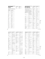
Содержание RDR VX555 - DVDr/ VCR Combo
Страница 62: ...2 22 2 22E MEMO ...
Страница 64: ...3 4E MEMO ...
Страница 66: ...4 1 DVD Main PCB 4 4 4 3 COMPONENT SIDE ...
Страница 67: ...4 6 4 5 CONDUCTOR SIDE ...
Страница 68: ...4 8 4 7 4 2 VCR Main PCB COMPONENT SIDE ...
Страница 69: ...4 10 4 9 CONDUCTOR SIDE ...
Страница 70: ...4 12 4 11 4 3 Function PCB COMPONENT SIDE COMPONENT SIDE ...
Страница 71: ...4 14 4 13 4 4 Front Jack PCB COMPONENT SIDE CONDUCTOR SIDE ...
Страница 72: ...4 16E 4 15 4 5 DV Jack PCB COMPONENT SIDE COMPONENT SIDE ...
Страница 74: ...5 4 5 3 5 1 S M P S VCR Main PCB ...
Страница 75: ...5 6 5 5 5 2 Power VCR Main PCB ...
Страница 76: ...5 8 5 7 5 3 Logic VCR Main PCB ...
Страница 77: ...5 10 5 9 5 4 A V VCR Main PCB ...
Страница 78: ...5 12 5 11 5 5 Hi Fi VCR Main PCB ...
Страница 79: ...5 14 5 13 5 6 MPEG Decoder DVD Main PCB ...
Страница 80: ...5 16 5 15 5 7 A V Decoder DVD Main PCB ...
Страница 81: ...5 18 5 17 5 8 In Out DVD Main PCB ...
Страница 82: ...5 20 5 19 5 9 DV HDMI DVD Main PCB ...
Страница 83: ...5 22 5 21 5 10 Front Timer Front Jack PCB DV Jack DV Jack PCB ...
Страница 84: ...5 24E 5 23 5 11 Function Function PCB ...
Страница 127: ...MEMO ...


