


1-2
11
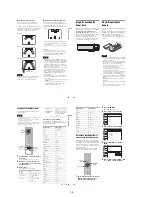
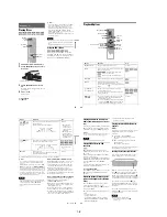
Sub-menu
The sub-menu appears when you select an item
from a list menu (e.g., a title from the Title List
menu), and press ENTER. The sub-menu displays
options applicable only to the selected item. The
displayed options differ depending on the
situation and disc type.
Select an option by pressing
M
/
m
and ENTER.
Example: The Title List menu
OPTIONS
The OPTIONS menu appears when you press
OPTIONS. You can search for a title/chapter/
track, check the playing and remaining time, or
change settings for audio/angle/subtitle. The
displayed options differ depending on the media
type.
Press
M
/
m
to select an option, press
<
/
,
to
select the desired item, and press ENTER.
Example: When you press OPTIONS while a
DVD VIDEO is playing.
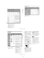
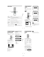
Selectable options
Selectable options on the System Menu differ
depending on the media type, disc condition, and
operating status.
Example: When a disc or a VHS tape is stopped.
*1
Unfinalized disc only
*2
With a disc inserted
To return to the previous display
Press
O
RETURN.
Notes
• The OPTIONS menu may not appear during DVD
recording.
• The System Menu does not appear when recording on
a DVD, or dubbing from VHS tape to a DVD.
• You cannot use the DVD or VIDEO buttons with the
System Menu turned on.
Title List (Original)
10:10 AM
No. Title
Length
Edit
01 LINE 1
>
01:29:03
02 LINE 1
>
00:31:23
03 LINE 1
>
01:59:00
04 LINE 1
>
00:58:56
LINE 1
May/02/2007
08:00 PM
T
1/4
Play
Title Erase
Chapter Erase
Protect
Title Name
A·B Erase
Divide Title
Options for the selected item
1/4
1/1
00:00:25
T
C
Title
Chapter
Time
Remain
Audio
Angle
00:01:30
Subtitle 2/2 ENG
1/1
ENG Dolby D2ch (1/1)
DVD
VIDEO
Type
Selectable option
+
RW
-RW
VR
*1
-RW
Video
*1
+
R
*1
*1
-R
VR
*1
*1
-R
Video
*1
*1
DVD
RAM
VCD
CD
DATA CD
DATA DVD
*2
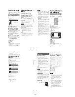
12
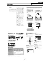
Hookups and Settings
Hooking Up the Recorder
Follow steps 1 to 7 to hook up and adjust the
settings of the recorder.
Notes
• Plug cords securely to prevent unwanted noise.
• See the instructions supplied with the components to be
connected.
• You cannot connect this recorder to a TV that does not
have a video input jack.
• Be sure to disconnect the power cord of each
component before connecting. Do not connect the
power cord until you reach “Connecting the Power
Cord” on page 20.
Step 1: Unpacking
Check that you have the following items:
• Audio/video cord
(phono plug
u
3
y
phono plug
u
3) (1)
• Remote commander (remote) (1)
• Set top box controller (1)
• Size AA (R6) batteries (2)
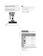
Step 2: Connecting the
Cable Box/Satellite
Receiver (Tuner)
This recorder does not include a TV tuner.
To record TV programs on this recorder, you need
to connect the recorder to a tuner that has audio/
video output jacks.
If you have been using your VCR connected to an
antenna, connect this recorder to your VCR using
an audio/video cord. In this way, you will be able
to record TV programs.
You cannot record on this recorder if you have:
– a cable box or satellite receiver without audio/
video outputs.
– cable with no cable box.
– antenna only (no cable TV).
In the cases above, contact your cable service or
satellite service company to see if they can
provide you with a compatible cable box or
satellite receiver.
Using the cable box/satellite
receiver control function
This function allows the recorder to control a
cable box or satellite receiver via the supplied set
top box controller. You can also use the recorder’s
remote control to change channels on the cable
box/satellite receiver whenever the cable box/
satellite receiver and the recorder are turned on.
To use the cable box/satellite receiver control
function, you need to:
– Check the brand code of your cable box/satellite
receiver. See “Cable Box/Satellite Receiver
Brand Code” (page 121).
– Connect the set top box controller (page 13).
– Set the brand code number and the recorder’s
input that is connected to the cable box/satellite
receiver (page 23).
After setting up the cable box/satellite receiver
control, check that the recorder can correctly
control the cable box or satellite receiver
(page 26).
13
Ho
o
kup
s
an
d
S
e
tt
in
g
s
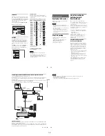
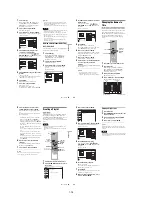
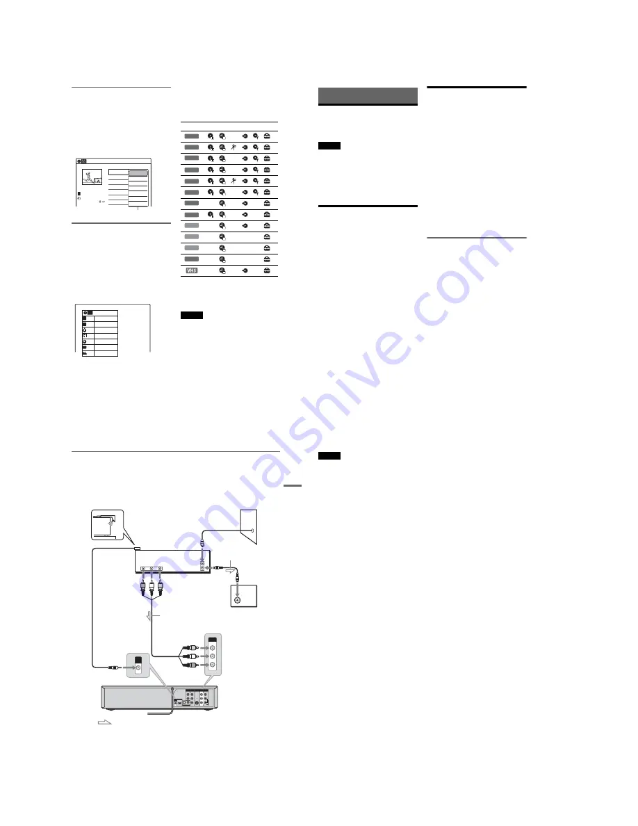
Connecting a cable box/satellite receiver and set top box controller
Connect the LINE IN jacks using an audio/video cord.
With this hookup, you can record any channel on the cable box or satellite receiver. Be sure that the cable
box or satellite receiver is turned on. This connection is necessary to use the Synchro-Rec function
(pages 51 and 80).
To watch cable or satellite programs, you need to match the input source on the recorder (L1) to the input
jack connected to the cable box or satellite receiver (LINE 1 IN).
Place the set top box controller near the remote sensor on the cable box/satellite receiver.
About AV path through
This recorder automatically sends the input signal from the LINE 1 IN jacks to the LINE OUT VIDEO/
AUDIO jacks without turning itself on.
When you connect a cable box or satellite receiver to the LINE 1 IN jacks and your TV to the LINE OUT
(VIDEO/AUDIO L/R) jacks (page 15), you can watch programs from a cable box or satellite receiver on
the TV even when the recorder is turned off.
L
R
VIDEO
AUDIO
LINE OUT
VIDEO
Y
L
PB
R
PR
AUDIO
LINE 1 IN
AUDIO OUT
S VIDEO OUT
COMPONENT
VIDEO OUT
DIGITAL AUDIO OUT
OPTICAL COAXIAL
HDMI OUT
SETTOP
BOX
CONTROL
ANT IN
R
L
AUDIO
OUT
VIDEO
OUT
TO TV
VIDEO
LINE 1 IN
AUDIO
SETTOP
BOX
CONTROL
Set top box
controller
(supplied)
Cable box/
satellite receiver
Antenna cable
(not supplied)
Wall
to antenna input
TV
Audio/video cord
(not supplied)
to SET TOP BOX
CONTROL
to LINE 1 IN
VCR-DVD recorder
: Signal flow
,
continued
14
Notes
• Synchro-Recording does not work with some tuners. For details, see the tuner’s operating instructions.
• AV path through function does not work for:
– Input signals from the LINE 2 IN jacks.
– Output signals to S VIDEO OUT, COMPONENT VIDEO OUT, or HDMI OUT jacks.
Содержание RDR VX555 - DVDr/ VCR Combo
Страница 62: ...2 22 2 22E MEMO ...
Страница 64: ...3 4E MEMO ...
Страница 66: ...4 1 DVD Main PCB 4 4 4 3 COMPONENT SIDE ...
Страница 67: ...4 6 4 5 CONDUCTOR SIDE ...
Страница 68: ...4 8 4 7 4 2 VCR Main PCB COMPONENT SIDE ...
Страница 69: ...4 10 4 9 CONDUCTOR SIDE ...
Страница 70: ...4 12 4 11 4 3 Function PCB COMPONENT SIDE COMPONENT SIDE ...
Страница 71: ...4 14 4 13 4 4 Front Jack PCB COMPONENT SIDE CONDUCTOR SIDE ...
Страница 72: ...4 16E 4 15 4 5 DV Jack PCB COMPONENT SIDE COMPONENT SIDE ...
Страница 74: ...5 4 5 3 5 1 S M P S VCR Main PCB ...
Страница 75: ...5 6 5 5 5 2 Power VCR Main PCB ...
Страница 76: ...5 8 5 7 5 3 Logic VCR Main PCB ...
Страница 77: ...5 10 5 9 5 4 A V VCR Main PCB ...
Страница 78: ...5 12 5 11 5 5 Hi Fi VCR Main PCB ...
Страница 79: ...5 14 5 13 5 6 MPEG Decoder DVD Main PCB ...
Страница 80: ...5 16 5 15 5 7 A V Decoder DVD Main PCB ...
Страница 81: ...5 18 5 17 5 8 In Out DVD Main PCB ...
Страница 82: ...5 20 5 19 5 9 DV HDMI DVD Main PCB ...
Страница 83: ...5 22 5 21 5 10 Front Timer Front Jack PCB DV Jack DV Jack PCB ...
Страница 84: ...5 24E 5 23 5 11 Function Function PCB ...
Страница 127: ...MEMO ...


