background image

45

Step 6: Configuring the Routing and Monitoring Screens

Obtaining a monitoring setup file

A monitoring setup file is required for each operation 
mode.
For details about obtaining a monitoring setup file, contact 
your Sony sales representative.

In cost priority mode, separate setup files must be used in 
the Network System Manager for OR1 and the Network 
System Manager for OR2.

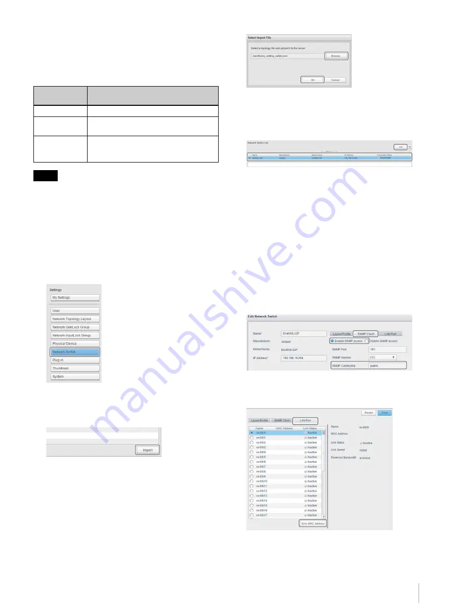
Importing a setup file

Use the following procedure to import a monitoring screen 
setup file into Network System Manager.

1

Click [Settings] > [Network Switch].

The [Network Switch List] screen appears.

2

Click the [Import] button.

The [Select Import File] dialog appears.

3

Click the [Browse] button, and select the setup file.

4

Click the [OK] button.

The imported setup file data (EX4550-32F) is 
displayed in [Network Switch List].

5

Select the imported data, and click the [Edit] button.

The [Edit Network Switch] dialog appears.

6

Select the [SNMP Client] tab, and configure the 
following items.

[Enable SNMP access]/[Disable SNMP access]: 

Select [Enable SNMP access].

[SNMP Community]:

Enter “public”.

[IP Address]:

Safety priority or uncompressed transmission 
priority
   192.168.10.254
Cost priority
   10.10.0.100

7

Select the [LAN Port] tab, and click the [Sync MAC 
Address] button.

8

Check that the MAC address is displayed, and click 
the [Save] button.

Operation 
mode

File name

Safety priority

monitoring_setting_safety.json

Cost priority

monitoring_setting_cost_or1.json
monitoring_setting_cost_or2.json

Uncompressed 
transmission 
priority

monitoring_setting_uncompression.json

Tip

Содержание NU-NM11B

Страница 1: ...Network System Manager System Integration Guide NU NM11B 2016 Sony Corporation 4 689 765 12 1 2017 08 ...

Страница 2: ... a DVI IP Converter 42 Step 6 Configuring the Routing and Monitoring Screens 43 Configuring the Routing Screen 43 Configuring the Monitoring Screen 44 Step 7 Collecting Logs 47 Collecting IP Converter Logs 47 Collecting Network System Manager Logs 48 Step 8 Checking System Settings and Device Connections Checklist 49 OR IP Solution System Checklist 50 Checklist Details 51 Step 9 Creating Backup Da...

Страница 3: ...an example system structure comprising two video output devices sources and two video input devices destinations In this manual OR represents an Operating Room in the OR IP Solution System System Components Device Description IP converter Device which converts between video signals and IP signals The following two types of IP converter are supported for the video interface SDI or DVI SDI NU IP40S ...

Страница 4: ...rk switch support information contact your sales representative OR controller NSM API client Network System Manager provides an API that enables control from an external controller For details about the API of Network System Manager contact your Sony sales representative Source SRC Device equipped with a video signal output endoscopic devices surgical field cameras PCs Destination DEST Device equi...

Страница 5: ...5 Overview In step 1 determine the number of devices required Next build the system using steps 2 to 9 The system structure in the following pages is described in the step sequence above ...

Страница 6: ...install the system 2 Determine the number of source devices and destination devices for each OR 3 Determine the number of source devices and destination devices mounted on trolleys for use in multiple ORs 4 Determine the video interface and video format of each source device and destination device Refer to the operating instructions of the IP converter and check whether connection with the IP is s...

Страница 7: ... If optical connectors are mounted on a wall use durable connectors This manual describes the use of the type 1 trolley configuration Determining the Operation Mode The system supports the following three operation modes Select the mode according to the application Safety priority Cost priority Uncompressed transmission priority You can specify a different operation mode for use in each OR Network...

Страница 8: ...tical fiber cables The same video signal is transmitted on both optical fiber cables to ensure the video signal is not interrupted if one of the cables is damaged or disconnected HD uncompressed 2 IP converter IP converter IP converter IP converter Optical fiber cables Video cables Network cables 4K compressed 2 Network switch NSM server Source 4K Source HD Destination Destination ...

Страница 9: ... is also interrupted Instead you can connect multiple IP converters to a single network switch and share the network switch between two ORs NSM server IP converter IP converter IP converter IP converter IP converter IP converter IP converter IP converter Optical fiber cables Video cables Network cables 4K compressed 1 Network switch Source 4K Source HD Source 4K Source HD Destination Destination D...

Страница 10: ...propriately Operation mode comparison table Customization of the operation mode If you want to customize the operation mode contact your Sony sales representative Customization examples Connecting more than 16 devices per OR Sharing a network switch between three or more ORs Sharing a network switch between two ORs in safety priority or uncompressed transmission priority operation mode IP converte...

Страница 11: ...erter generates a network sync signal synchronized to the input video signal and the followers operate in sync with the network sync signal The video signal transmission delay time is shorter because the input video signal and network sync signal are synchronized On the other hand when switching the video signal transmitted to a destination IP converter the switching time is longer because the IP ...

Страница 12: ...ot synchronized In Network GenLock mode if the IP converter designated as the sync leader is not connected syncing of the video signals fails and the system may become unstable Ensure that the IP converter designated as the sync leader cannot be turned off during operation Accordingly do not use an IP converter mounted on a trolley that is moved between ORs as the sync leader When sharing trolley ...

Страница 13: ... IP converter Follower IP converter Follower Source 4K Source 4K Source HD Destination Destination Destination Trolley OR1 Trolley IP converter Leader Note Device Requirement IP converter Number of source devices and destination devices used in all ORs including devices used on trolleys Add 1 if using an IP converter as a dedicated sync leader in Network GenLock mode Network System Manager NSM ser...

Страница 14: ...nd Network System Manager If there are any errors with the unit restart the unit If the problem persists follow the instructions for resolving the issue in System Fault Troubleshooting page 61 If the IP converters and Network System Manager operate continuously without being turned off occasionally a malfunction may eventually occur In this case turn the system off temporarily and restart the syst...

Страница 15: ...r details about installation refer to the operating instructions for the network switch and options The description in this document is based on the Juniper Networks EX4550 32F network switch For the latest network switch support information contact your sales representative The network switch may take a few minutes for booting to finish Wait until the MST status LED turns on solid green Device De...

Страница 16: ...ared between two ORs and each OR is set a unique VLAN ID In addition separate MGMT VLANs must be created and connected with Network System Manager Connect one of the 10GBASE T ports used for the MGMT VLAN to the MGMT port using a network cable Category 5e or higher The assigned VLAN ID VLAN name network address and network switch IP address are given below The VLAN settings can be configured for a...

Страница 17: ...urity Do not connect to the Internet To connect to the Internet contact your Sony sales representative Host address Description 1 to 9 IP addresses for OR controllers and NSM API clients These addresses are user configurable 10 Reserved for future functions 11 IP address for the NSM server 12 to 20 Reserved for future functions 21 to 70 IP addresses for IP converters on trolleys up to 50 addresses...

Страница 18: ...IP converter fixed OR1 OR2 Trolley 192 168 10 71 Main 192 168 11 71 Sub 192 168 10 72 Main 192 168 11 72 Sub 192 168 10 11 Main 192 168 11 11 Sub 192 168 10 1 Main IP converter fixed IP converter fixed 192 168 10 11 Main 192 168 11 11 Sub 192 168 10 1 Main NSM server OR controller NSM server OR controller Network switch Network switch 192 168 10 71 Main 192 168 11 71 Sub 192 168 10 72 Main 192 168...

Страница 19: ...rity operation mode IP converter fixed IP converter fixed OR1 OR2 Trolley 192 168 10 71 192 168 10 72 192 168 10 11 192 168 10 1 NSM server OR controller IP converter fixed IP converter fixed 192 168 10 71 192 168 10 72 192 168 10 11 192 168 10 1 NSM server OR controller Network switch IP converter trolley IP converter trolley 192 168 10 21 192 168 10 22 10 10 0 101 10 10 0 102 ...

Страница 20: ...e RJ45 to RS232C adapter cable to the Console port CON For PCs without a serial port use a USB serial adapter cable 2 Connect the power cord and start the network switch 3 Turn the PC on and launch PuTTY 4 Click Connection Serial on the Category pane The serial port setup dialog appears 5 Configure the following items Serial line to connect to Set the communication port Speed baud 9600 Data bits 8...

Страница 21: ...8 Press Ctrl D 9 Enter commit 10 Check that configuration check succeeds and commit complete appear in the terminal window 11 Enter exit 12 Enter request system configuration rescue save 13 Enter show system alarms 14 Check that No alarms currently active appears in the terminal window 15 Enter exit 16 Enter exit Tip Tip root RE 0 cli master 0 root configure Entering configuration mode master 0 ed...

Страница 22: ...g a network cable Category 5e or higher On the network switch connect a network cable to the network port of the 10GBASE T expansion module Also the NSM server and network switch must be connected using two network cables The connection method in cost priority mode varies from that used in safety priority or uncompressed transmission priority mode Connect as shown in the following diagrams Safety ...

Страница 23: ...mask 255 255 255 0 Default Gateway Setup not required Cost priority Main IP address 192 168 10 11 Subnet mask 255 255 255 0 Default gateway Enter the address of the network switch see page 16 MGMT IP address 10 10 0 101 or 10 10 0 102 see page 19 Subnet mask 255 255 255 0 Default Gateway Setup not required Leave other settings with their default values 5 Click the OK button Setting the DHCP server...

Страница 24: ...type Byte Array Turn the checkbox on Code 240 4 In the DHCP dialog right click IPv4 and select New Scope The New Scope Wizard dialog appears 5 Set the IP address range as described in IP addresses page 17 After setting the IP address range click the Next button Create a scope by following the instructions in the wizard In safety priority or uncompressed transmission priority operation mode create ...

Страница 25: ...tion disc Follow the instructions in the wizard to install the software 2 When installation is finished restart the OS Network System Manager is registered as a Windows service and will start automatically when the OS starts Configuring the hosts file Configure the hosts file so that a warning is not displayed each time Network System Manager is accessed from a browser It is recommended that you m...

Страница 26: ... Always change the password of the default account page 27 You can register the URL as a browser bookmark for convenience Placing a check mark in the Remember the credentials to skip the login checkbox will automatically log in when you enter the URL subsequently Checking the version information You can check the version information for Network System Manager 1 Click the Help button and select Abo...

Страница 27: ...d click the Activate button A confirmation message appears 5 Click the Yes button The installed license is activated Changing the Password of the Default Account Use the following procedure to change the password of the default account 1 Click Settings My Settings The My Settings screen appears 2 Change the password using Change Password Old Password Enter the current password New Password Enter t...

Страница 28: ...gin password 4 Click the Save button The user account is registered and is displayed in User List Registering a user account in a workgroup You can use a workgroup by registering a user account in the workgroup using the following procedure 1 Click Workgroup Settings User Assign The User Assign List screen appears 2 Select a user in User List to Assign and click the button User role Available func...

Страница 29: ...e registration is completed Deleting a user account Use the following procedure to delete a user account 1 Select the user account to delete on the User List screen and click the Delete button A confirmation message appears 2 Click the Yes button The selected user account is deleted from the list Provide appropriate user account management Note ...

Страница 30: ...e precedence over the settings from Network System Manager Down convert setting ON Stereoscopic VPID 0x8f For details about setting DIP switches refer to the operating instructions for the IP converter Resetting an IP converter Use the following procedure to reset an IP converter Reset as required 1 Set DIP switch 8 in bank 3 to ON and turn on the IP converter 2 After the IP converter starts turn ...

Страница 31: ...ected Check the following if an IP converter is not displayed in Physical Device List or if the Connection Status is Disconnected Are the MAIN and SUB connections reversed see page 30 Is the DHCP server configured incorrectly see page 23 Serial Number is the number displayed on the bottom of the IP converter Configuring a Workgroup An IP converter must be registered in a workgroup in order to cont...

Страница 32: ...ecking the basic operation described in Basic IP Converter Configuration Operations page 33 perform the following initialization for all IP converters IP converter configuration flow Initializing aSet a name Set the names of the IP converter For details about configuration see Setting the name page 35 bSet the IP address Set IP address of the IP converter For details about configuration see Settin...

Страница 33: ...nverter For details about configuration see Setting the video interface page 38 Basic IP Converter Configuration Operations Configure the various settings of an IP converter using Network System Manager IP converter settings are broadly divided into two types NMI Networked Media Interface device common settings and IP converter specific settings You can configure settings on the following screens ...

Страница 34: ...y starts streaming when the settings are applied to the IP converter If you want to continue the configuration the AV stream must be stopped again Applying IP converter settings After changing the IP converter settings on the Edit Virtual Device screen and Detail setting screen apply the settings to the IP converter The operation on the Edit Virtual Device screen and Detail setting screen varies a...

Страница 35: ... not be reflected on the settings screen If this occurs click the Synchronize button again IP Converter Configuration Procedure Configure the various settings of an IP converter using the Edit Virtual Device screen and Detail setting screen in Network System Manager For details about displaying each screen preparations before configuration and writing configuration data see Basic IP Converter Conf...

Страница 36: ...If Use the following IP address is selected for the MAIN address also select Use the following IP address for the SUB address For connections using only one optical fiber cost priority when changing the sub address setting select Disable LAN and Use the following IP address and specify an IP address Setting the system frequency You can set the system frequency of an IP converter to 25 Hz or 29 97 ...

Страница 37: ...ressed transmission of 4K video This configuration can be enabled only for an IP converter configured for connection with a source device see page 36 Select Uncompressed under 4K Quality on the Video tab of the Detail setting screen Disabling 4K uncompressed transmission Select Standard under 4K Quality on the Video tab of the Detail setting screen Enabling 4K uncompressed transmission DVI IP conv...

Страница 38: ... display the video on an HD monitor The IP converters are equipped with a down convert function which can be enabled disabled from Network System Manager This configuration can be enabled only for an IP converter configured for connection with a destination device see page 36 Set Down Convert to Enable on the Video tab of the Detail setting screen to enable the down convert function Select Disable...

Страница 39: ...he sync mode after previously setting the sync mode all IP converters must first be deleted from the sync group Deleting IP converters from a Network InputLock group 1 Display the Assign Virtual Network InputLock Module dialog See steps 1 and 2 in Setting Network InputLock mode page 39 2 Turn the checkboxes on for all IP converters displayed in Virtual Network InputLock Module List and click the D...

Страница 40: ...ing Network GenLock mode Use the following procedure to set the sync mode to GenLock 1 Click Settings Network GenLock Group The Network GenLock Group List screen appears 2 Click the Create button The Create New Network GenLock Group dialog appears 3 Configure the following items and then click the Assign button Name Set the name of the Network GenLock group Duplicate Turn the checkbox on if using ...

Страница 41: ...ers button The Assign Virtual Follower Network GenLock Module dialog appears 7 Turn the checkboxes on for all IP converters displayed in GenLock Module List and click the button The IP converters are registered in Virtual Follower Network GenLock Module List 8 Click the Close button 9 Click the Apply button 10Activate the workgroup see page 32 When sharing trolley devices between ORs the IP addres...

Страница 42: ... supports HD signal input output use one SDI cable as shown below Connect the SDI cables to the SDI input output A on the IP converter Take care not to make a mistake when connecting SDI cables Connecting to a DVI IP Converter Connection with a source device When connecting an IP converter to a source device connect the DVI input and HDMI input connectors of the IP converter as shown in the follow...

Страница 43: ...is used to perform video path switching You can set the name and icon of an IP converter displayed on the routing screen Setting the name and icon of an IP converter Use the following procedure to set the name and icon of an IP converter displayed on the routing screen 1 Click the Workgroup button The Workgroup Selection screen appears 2 Click the Default Workgroup button This enters the workgroup...

Страница 44: ...p Settings Changing Interface Names and Image Display 7 Click the Routing button The routing screen appears Check that the name and icon displayed has been updated The name and icon settings will be reset if the IP converter is deleted from a workgroup deleted from Virtual Device List Testing the video path switching Click the intersecting frame of a source device and destination device on the rou...

Страница 45: ...se button and select the setup file 4 Click the OK button The imported setup file data EX4550 32F is displayed in Network Switch List 5 Select the imported data and click the Edit button The Edit Network Switch dialog appears 6 Select the SNMP Client tab and configure the following items Enable SNMP access Disable SNMP access Select Enable SNMP access SNMP Community Enter public IP Address Safety ...

Страница 46: ...creen 1 Click Settings Network Topology Layout The Network Topology Layout screen appears 2 Click the Create button The topology diagram appears 3 Select the layout method in Layout Column is selected for this example The layout of the topology diagram is updated 4 Click the Save button 5 Click the Monitoring button The monitoring screen appears Check that the topology diagram has the layout speci...

Страница 47: ...lowing procedure 1 Deactivate the workgroup see page 32 2 Click Settings Physical Device The Physical Device List screen appears 3 Select an IP converter to link and click the Detail button The Detail of Physical Device dialog appears 4 Select the Maintenance tab and click the Add button If optical fiber cable redundancy is disabled click once If enabled click twice The Syslog list is added 5 Sele...

Страница 48: ... details about the location for saving IP converter logs refer to the operating instructions for the installed Syslog server A sample IP converter log entry is shown below Jan 1 00 30 35 192 168 10 50 NMI 546 NU IP40S 9005029 00000000 request return OK Collecting Network System Manager Logs Network System Manager logs are saved in the following folder C Sony LSM logs Adjusting the clocks on the NS...

Страница 49: ...8 Checking System Settings and Device Connections Checklist After constructing the system check that each device is configured and connected correctly Print out the checklist check each item and store the results For details about checking items see Checklist Details page 51 ...

Страница 50: ...y for all IP converters is set to Uncompressed 6 Check the sync mode settings Network InputLock mode Check that GenLock Module Status is set to Locked on the source IP converters 7 Check the sync mode settings Network GenLock mode Check that the IP converter configured as the leader is correct in Virtual Leader Network GenLock Module List on the preview screen Check that GenLock Module Status is s...

Страница 51: ...the LED is lit red or yellow Refer to the following sections to perform configuration again Preparing a Network Switch page 15 Configuring a Network Switch page 20 Note The description in this document is based on the Juniper Networks EX4550 32F network switch For the latest network switch support information contact your sales representative 2 Check the IP converter LEDs Check the SYSTEM indicato...

Страница 52: ...rations page 33 Check that the Enable hitless failover checkbox is on Note Check the optical fiber cable redundancy settings of all IP converters 5 Check the 4K uncompressed transmission settings of the IP converters This check item is only required if operating the system in uncompressed transmission priority mode only Check the 4K Quality setting of an IP converter using the Edit Virtual Device ...

Страница 53: ... in Setting the Sync Mode page 39 Check the Network GenLock mode settings on the Network GenLock Group List screen of Network System Manager For details about displaying the screen see Setting Network GenLock mode page 40 When sharing trolley devices between ORs check that the IP address of the Network GenLock leader and the PTP domain number of the Network GenLock group is the same as for the OR ...

Страница 54: ...screen Check the display on the monitoring screen of Network System Manager For details about displaying the screen see Configuring the Monitoring Screen page 44 Check the connection status on the Network Topology Layout screen and check that no errors have occurred No Check item Description ...

Страница 55: ...ager License page 26 However these steps are not required if replacing the hard disk only Acquiring Backup Data This section describes how to create a full backup of the NSM server and save the backup data to a hard disk Individual files and folders cannot be recovered from backup data created using this procedure The backup data created can be used for total system recovery only Use the following...

Страница 56: ...ed appears in the Backup Once Wizard dialog click the Close button Recovering from a Backup This section describes how to perform a bare metal recovery after replacing a hard disk using a full backup saved on a hard disk Use the following procedure to perform a bare metal recovery The screen display will vary depending on the usage environment 1 Start the server from the Windows Server 2012 instal...

Страница 57: ...screen appears 4 Click System Image Recovery The Re image your computer dialog appears 5 Select Use the latest available system image recommended and click the Next button 6 Turn the Format and repartition disks checkbox on and click the Next button You can click the Exclude disks button to select disks to exclude from the restore process 7 Check the settings and click the Finish button Tip ...

Страница 58: ... Creating Backup Data A warning message appears 8 Check the message contents and click the Yes button if there is no problem The restore process starts When restoration finishes the system automatically restarts ...

Страница 59: ...der see page 30 dTurn on the other target devices for operation eCheck that the number of notifications is zero on the GUI screen of Network System Manager fCheck the following items on the routing screen of Network System Manager Background color of source device icons is light gray All name tabs are blue gCheck the following items on the routing screen of Network System Manager Background color ...

Страница 60: ...and the NSM server bTurn off the network switch using the manufacturer specified method Turning Off a Network Switch If a network switch is turned off while any IP converters are still operating the video will not lock to the sync signal the next time the network switch is started If video syncing cannot be obtained restart the IP converters ...

Страница 61: ... about fault detection and troubleshooting for each device refer to the operating instructions or service manual of each device Notification List screen Network Topology Monitoring screen Error display In the following description the content of an error message is represented by characters The content will vary depending on the type of error The display of a The device detected status error messa...

Страница 62: ...tification screen Recovery method Turn off the IP converter Unlink the virtual device of the GenLock module of the IP converter on which the error occurred See Changing a Network GenLock Follower Device page 70 In Settings Physical Device Physical Device List in Network System Manager select and delete the IP converter on which the error occurred Turn on the IP converter Re register the IP convert...

Страница 63: ... the NSM server If the error persists after restarting contact your Sony sales representative Faults Preventing Connection of IP Converters Error detection A device error is detected and displayed on the Notification screen The background color of the device icon of the IP converter on which the fault error occurs changes to yellow and a mark is displayed on the icon on the Network Topology Monito...

Страница 64: ...or the IP converter When finished restart the IP converter If the problem persists the IP converter may have failed Contact your sales representative Replace with a spare unit if one is available as described in Replacement Procedures when IP Converter Fault Occurs page 67 Faults with Network GenLock Leader Devices Error detection A lock error is detected and displayed on the Notification screen T...

Страница 65: ...em Fault Troubleshooting The error status of the Network GenLock group is displayed on the Settings System Status screen Recovery method Follow the procedure in Changing a Network GenLock Leader Device page 68 ...

Страница 66: ...hanges to yellow on the Network Topology Monitoring screen Continuous operation Continuous operation is supported as long as an error does not occur with the NSM server or IP converters Recovery method Check the error details of the error message on the Notification List screen of Network System Manager and check the network switch If the network switch has failed contact the sales representative ...

Страница 67: ...hich a fault has occurred on the Virtual Device List screen and click the Deactivate button 2 Click to open the virtual device select the physical device linked to the virtual device and click The link between the physical device and the virtual device is removed 3 Select a new physical device and click The virtual device and new physical device are linked together ...

Страница 68: ...P domain number of the Network GenLock group must be the same as for the OR 1 Click beside the Default Workgroup button on the Workgroup Selection screen and select Deactivate The workgroup is deactivated 2 Select the Network GenLock group in which a fault has occurred on the Network GenLock Group List screen and click the Edit button The Edit Network GenLock Group dialog appears 3 Click the butto...

Страница 69: ... Network GenLock leader is deleted 4 Click the Assign button The Assign Virtual Leader Network GenLock Module dialog appears 5 Select the new leader and click the Assign button 6 Click the Save button 7 Select the Network GenLock group and click the Apply button ...

Страница 70: ... 8 Click beside the Default Workgroup button on the Workgroup Selection screen and select Activate The workgroup is activated Changing a Network GenLock Follower Device 1 Deactivate the workgroup See step 1 in Changing a Network GenLock Leader Device page 68 ...

Страница 71: ...ollower Network GenLock Module dialog appears 3 Select the IP converter on which a fault has occurred and click the Delete button The selected IP converter is deleted from the Virtual Follower Network GenLock Module List 4 Select a new IP converter in the GenLock Module List and click The new IP converter is registered in the Virtual Follower Network GenLock Module List 5 Click the Close button 6 ...

Страница 72: ...rk InputLock Group in which a fault has occurred on the Network InputLock Group List screen and click the Assign Members button The Assign Virtual Network InputLock Module dialog appears 3 Select the IP converter on which a fault has occurred and click the Delete button The selected IP converter is deleted from the Virtual Network InputLock Module List 4 Select a new IP converter in the GenLock Mo...

Страница 73: ...73 Replacement Procedures when IP Converter Fault Occurs 5 Click the Close button 6 Click the Apply button 7 Activate the workgroup See step 8 in Changing a Network GenLock Leader Device page 68 ...

Страница 74: ...lect the IP converter to add from Physical Device List on the Virtual Device List screen and click The selected IP converter is registered in the Virtual Device List 2 Select the newly added IP converter and click the Activate button GenLock Settings 1 Deactivate the workgroup See step 1 in Changing a Network GenLock Leader Device page 68 ...

Страница 75: ...Assign Virtual Follower Network GenLock Module dialog appears 3 Select a new IP converter in the GenLock Module List and click The new IP converter is registered in the Virtual Follower Network GenLock Module List 4 Click the Close button 5 Click the Apply button 6 Activate the workgroup See step 8 in Changing a Network GenLock Leader Device page 68 ...

Страница 76: ...2 Select Default Network InputLock Group on the Network InputLock Group List screen and click the Assign Members button The Assign Virtual Network InputLock Module dialog appears 3 Select a new IP converter in the GenLock Module List and click The new IP converter is registered in the Virtual Network InputLock Module List 4 Click the Close button ...

Страница 77: ...77 IP Converter Expansion Procedures 5 Click the Apply button 6 Activate the workgroup See step 8 in Changing a Network GenLock Leader Device page 68 ...

Страница 78: ...Sony Corporation Sony Corporation 1 7 1 Konan Minato ku Tokyo 108 0075 Japan ...

Отзывы: