44
Step 6: Configuring the Routing and Monitoring Screens
4
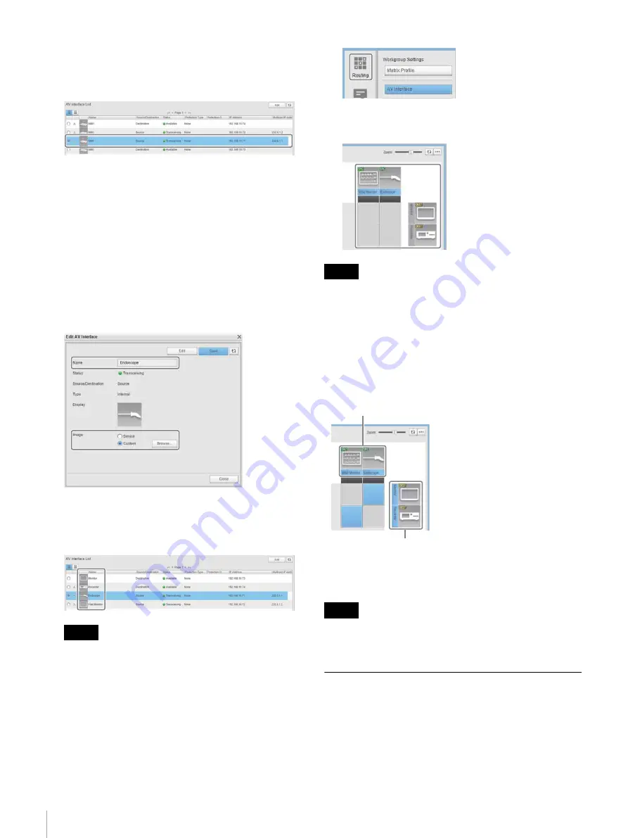
Select the IP converter you want to change in [AV
Interface List], and click the [Edit] button.
Check the IP address when selecting the IP converter.
The [Edit AV Interface] dialog appears.
5
Set the name and icon of the IP converter, and click the
[Save] button.
[Name]:
Set the name of the IP converter displayed on the
routing screen.
[Image]:
Set the icon of the IP converter displayed on the
routing screen. Select [Custom], click the
[Browse] button, and select the desired icon
image.
6
Click the [Close] button.
Check that the name and icon displayed in the [AV
Interface List] has been updated.
You can register additional icon images if you want to
use an icon other than the default icon. For details,
refer to the Help of the Network System Manager
(Workgroup Settings > Changing Interface Names and
Image Display).
7
Click the [Routing] button.
The routing screen appears. Check that the name and
icon displayed has been updated.
The name and icon settings will be reset if the IP converter
is deleted from a workgroup (deleted from [Virtual Device
List]).
Testing the video path switching
Click the intersecting frame of a source device and
destination device on the routing screen to switch the video
path.
For details about operations on the routing screen, refer to
the User’s Guide for Network System Manager.
The routing screen is not intended to be used to switch the
video path during a surgical operation.
Configuring the Monitoring Screen
The monitoring screen is used to check the connection
status of the network switch and various devices.
Import the setup file for the operation mode determined in
“Determining the Operation Mode” (page 7)
Network System Manager and configure the display layout
of the monitoring screen.
Tip
Note
Note
Source
Destination


