21
7. Secondary Power Supply - HA-3 & RA-5A Chassis
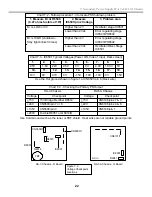
Chart 7-1 - Items Needed to Start the Secondary Power Supply
Checkpoint (use Hot Gnd except noted)
Item
HA-3 Direct View
RA-5A PJ TV
From
Purpose
340Vdc (B+)
D board
CN6501/pin 1 /
Fusible R6526
G board
Fusible R6041
Bridge Rectifier D6530 Powers the Driver/Output
Pri Pre 15V
voltage
D board
CN6501/pin 5
G board
IC6001/pin 8
Primary Power Supply
secondary – Pri Pre
Starts the oscillator when
more than 15.6Vdc.
Main Relay
voltage
D board
CN6504/pin 2 =
4.9Vdc (cold Gnd)
G board
CN6101/pin 6 =
5V (cold Gnd)
Main Micro IC001 (B
board)
Enables Sec PS Osc
IC6501 when HIGH
Surge Relay D board
PH6503/pin 4 =
6.3Vdc
G board
PH6003/pin 4 =
4.5Vdc
Primary Power Supply
secondary -Sub 7V or
Sub 6.5V
Stop the secondary PS if
the Surge Relay does not
close after power ON.
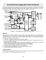
Figure 7-2
Checkpoint
Locations
FBT
HA-3 Chassis - D Board
PH6503
4
CN6504/1
3
CN6501/6
Hot GND
CN6501/6
PH6003
3 4
AC in
IC6001
R6041
RA-5A Chassis - G Board
Regulation
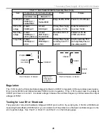
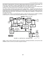
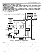
The +135V line to the Horizontal Output stage is fed back to IC6501 for regulation of the secondary power supply.
Error Control IC6503 and Optical Isolator PH6502 control regulation. If the +135V output rises, the voltage at
IC6501/pin 2 lowers to correct. A reduced voltage increases the oscillator frequency and decreases the output
voltages of T6501.
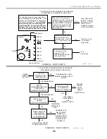
Testing for Low B+ or Shutdown
The typical error correction feedback voltage at IC6501/pin 2 is 2Vdc. By verifying the +135V B+ at R6598 and
measuring the feedback at IC6501/pin 2, you can determine if the problem is in the basic oscillator stage or in the
error regulator stage. See Chart 7-2, Chart 7-3 and Chart 7-4 on the following page:
Содержание KD-34XBR2 - 34" Hdtv Fd Trinitron Wega
Страница 77: ...74 RA 5A Chassis Board Layout ...
Страница 108: ...APPENDIX ...

