18
6. Primary Power Supply - HA-3 & RA-5a Chassis
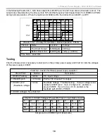
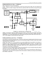
In the following Waveform 6-1, both drive outputs from IC6001/pins 12 and 16 are shown (channels 1 and 2). The
outputs are complementary, the duty cycle is 50% and the frequency has dropped down from 200kHz to 85kHz
during normal operation. When the top Driver (Q6002) is ON, the bottom Driver (Q6001) is OFF.
Ch 1
Ch 2
P M 3 3 9 4 , F L U K E & P H I L I P S
c h 1 : p k p k = 3 2 5 V
c h 1 : f r e q = 8 4 . 8 k H z
C H 1 ! 1 0 0 V =
C H 2 ! 5 . 0 0 V = M T B 2 . 0 0 u s - 1 . 1 8 d v c h 1 -
1
2
T
Waveform 6-1 - Primary PS Oscillator - Normal operation - 85kHz
Channel
Name
Location
Voltage
1
Top Driver Output
Q6002/gate
340Vp-p
2
Bottom Driver Out
Q6001/gate
12Vp-p (4.6Vdc)
Time base = 2usec/div.
Testing
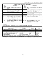
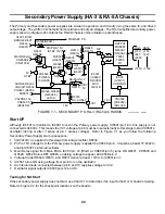
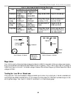
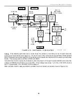
Chart 6-2 shows what is necessary to start and run the primary power supply and Chart 6-3 lists the voltages
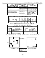
of the power supply’s IC6001.
Chart 6-2 - Checks for Primary power supply operation
Check Point
Normal
Description
1. R6006 (Fusible)
340Vdc
P.S. Input voltage
2. CN6005/ pin 5
>+15.6Vdc
Pri-Pre 15V. Checks P.S. Output
3. IC6001/ pin 2
(Feedback voltage)
1.9Vdc
Feedback Voltage. Troubleshooting - If step 2 voltage is low,
measure IC6001/pin 2. If pin 2 is High (4V) - problem is
around IC6001. If pin 2 is Low (0-1V), problem is the
feedback path IC6003, PH6001.
4. IC6001 voltages. See chart 6-3.
Chart 6-3 - IC6001 Voltages (Power ON, Video 1 input, Dark screen)
1.
2.
3.
4.
5.
6.
7.
8.
9.
3.0V
1.8V
2.2V
2.5V
0V
0V
4.5V
18.4V 0V
10.
11.
12.
13.
14.
15.
16.
17.
18.
10V
0V
4.5V
-0.2V -28V
-32V
-32V
-0.3V
313V
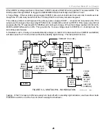
Hot ground is at CN6501/pin 6 (black wire).
Содержание KD-34XBR2 - 34" Hdtv Fd Trinitron Wega
Страница 77: ...74 RA 5A Chassis Board Layout ...
Страница 108: ...APPENDIX ...

