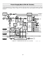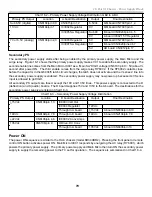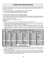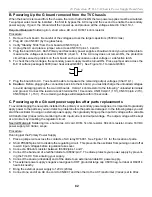
91
20. RA-5A Chassis Protection Block
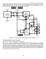
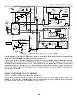
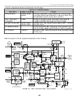
Testing - At power ON, 15v and -15V to the vertical output IC5004/pins 2 and 4. This voltage comes from
the secondary power supply on the G board. Then look for vertical drive signal at CN8006/pin 3 and 5. It is
possible to have reduced vertical deflection if one drive input is missing.
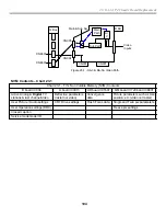
FIGURE 20-8 - PROTECTION - 4X INDICATION - RA-5 CHASSIS
IC5004
V OUT
LA78045
IC001
MAIN MICRO
M306V2MF
3
5
B19
26
IC3006
VIDEO
PROCESSOR
CXA2150AQ
25
24
52 53
7
1
7
2
4
35
5
+15V
-15V
FROM
SEC P.S
(GBD.)
R055
S DATA
R069
STBY LED
AC RELAY
(B BD.)
S CLK
CN013/
CN3022
+
- V
DRIVE
V PROTECT
CN3005/
CN8006
CN3005/
CN8004
D BD.
B BD.
A BD.
1
3
1
3
1
3
B
G
R
R8040
220
Q8001
BUFF.
R8036
R8039
2.2
D8001
5.6V
R8015
V DY
CN8009
CN8008
CN8007
8/31/01
30TVP12 1346
B19
A20
31
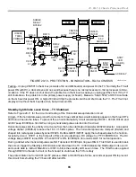
Standby light blinks five times - Blanking
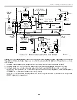
Refer to Figure 20-9 for this circuit description and testing.
Circuit - Three IK pluses are measured by Video Processor IC3006 as they return into pin 58. Each pulse
corresponds to the efficiency of each CRT cathode and therefore is used to adjust the RGB gain within IC3006 to
maintain color balance while the TV is operating (dynamic adjustment). The IK signals originate from IC3006 as
three bright lines in the vertical-blanking interval at lines 19-21. As the picture tube ages, the Ik signals may fall
below the threshold for automatic balance adjustment, causing IC3006 to mute/blank the substandard picture.
Although the picture is blanked, the IK pulses still output IC3006 and the three return IK pulses to IC3006/pin 58
are still operational as long as the TV is ON.
Содержание KD-34XBR2 - 34" Hdtv Fd Trinitron Wega
Страница 77: ...74 RA 5A Chassis Board Layout ...
Страница 108: ...APPENDIX ...

