55
11. Video Process - HA-3 and RA-5A Chassis
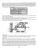
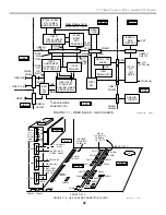
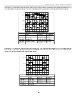
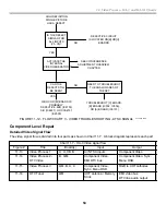
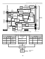
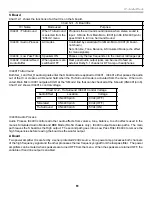
Chart 11-8 shows the main and sub video signal flow through the B board.
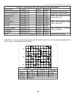
Chart 11-8 – Video Process 1 Signal Flow
IC
Name
Board
Function
Mode used
IC401
A/V Sw
B
Selects Main & Sub video inputs
When NTSC inputs are selected
Main Path
IC501
3D Comb Filter B
Separates the luminance form the
chroma.
All NTSC modes except S video
IC207
Main Y/Ct
B
Selects input component video 5,
6, or composite video from IC501.
Adds Closed Caption graphics
All NTSC modes
IC205
Main Sw
B
Swaps Twin View pictures back to
original position
All NTSC modes
Sub Path
IC204
Sub Comb
Filter
B
Separates the luminance from the
chroma.
Twin View
IC202
Sub Y/Ct
B
Selects input component video 5,
6, or composite video from IC501.
Adds Closed Caption graphics
Twin View
IC201
Sub Sw
B
Swaps Twin View pictures back to
original position
Twin View
IC200
Component
Interface
B
Selects NTSC sub video or HD
video 5, 6.
Twin View and HD video input
Video Process 2
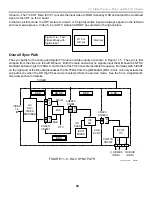
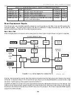
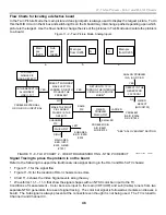
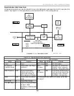
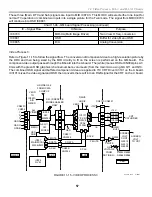
The main and sub NTSC component video signals from the B board enter the QM board for processing as listed
in Chart 11-9a. The signal flow is joined by the DTV tuner signal shown in Figure 11-15. All three signals flow into
the MID IC8703 for selection.
Содержание KD-34XBR2 - 34" Hdtv Fd Trinitron Wega
Страница 77: ...74 RA 5A Chassis Board Layout ...
Страница 108: ...APPENDIX ...


