5
2. New Features
Setup Menu
Refer to Figure 2-7 for a sample setup menu page.
Select Out - Selects Monitor for the same screen pix, TV for tuner, or
Video 1-4 regardless of what you are watching.
i Link Setup - Allows you to select a product like a cable box, which is
connected to the rear panel i Link (IEEE1394) jack.
i Link Standby - Allows the TV to remain at a power level between
standby and ON so an i Link device can power this TV ON.
Vertical Correction - Vertical position (centering)
Factory Reset – Clears all user settings and the active TV channels found
so only channels 2-13 are loaded. The TV shuts off momentarily and
loads the defaults at turn ON.
i LINK
i Link
and Fire Wire
are trade names for the IEEE-1394 high-speed communications standard that can
support digital video, audio and data. It uses transaction-based packet technology to communicate between
devices. This standard was developed to help bridge the gap between PCs and consumer electronic products.
Compatibility
The purpose of i Link is to transmit and receive high-speed data. The data may include digital audio and video
data as well as communications data in the ideal arrangement. In this early i Link acceptance stage, no digital
video or audio input is possible with this TV. Communications with this TV is limited to operation with the Sony
CableVision cable box currently used in NYC. Therefore, the following information shows how to connect i LINK
devices and what this TV does with an i LINK connected device.
Connection for Speed
The IEEE-1394 allows the data transmission speed to vary between devices, but the proper connection will
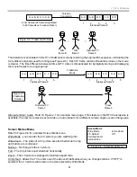
improve communications speed. In Figure 2-8, the PC or scanner would have no trouble communicating with the
camcorder at a rate of 100 Mb/s. However, the scanner could not communicate with the PC at its top data rate of
200 Mb/s because the path between the two contains a 100 Mb/s device (the camcorder). The maximum data
rate that can be achieved through another device is limited to the speed of that device.
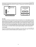
In Figure 2-9, the PC and the scanner would be able to communicate at the scanner’s top rate of 200 Mb/s. It is
important that when an IEEE-1394 network is set up, that high-speed devices are connected to high-speed
devices and lower speed devices are placed at the end of the chain.
Figure 2-7 - Setup Menu
Setup
Caption Vision
Off
Select Out
Monitor
Video Input
Language
i Link Setup
i Link Standby
Off
Set Clock/Timers
Vertical Correction
Tilt Correction
Demo
Factory Reset
PC
400Mb/s
Camcorder
100 Mb/s
Scanner
200 Mb/s
Figure 2-8 - Bandwidth limited by slower device
PC
400Mb/s
Camcorder
100 Mb/s
Scanner
200 Mb/s
Figure 2-9 - Improved Hookup
Содержание KD-34XBR2 - 34" Hdtv Fd Trinitron Wega
Страница 77: ...74 RA 5A Chassis Board Layout ...
Страница 108: ...APPENDIX ...


