20
7. Secondary Power Supply HA-3 & RA-5A Chassis
Secondary Power Supply (HA-3 & RA-5A Chassis)
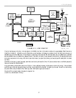
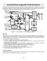
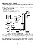
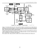
The Primary and Secondary power supplies are similar in operation and circuitry using the same IC and driver/
output stage. They differ in schematic nomenclature and output voltages. The HA-3 simplified secondary power
supply shown in diagram 24 contains the RA-5A chassis nomenclature in parentheses.
PH6503,
(PH6003)
ISOLATE
Q6526, Q6529,
(Q6004-5)
LATCH
1
18
16
12
8
4
3
IC6501,
(IC6001)
DRIVER
MCX
33001D
R6517
(R6017)
2
2
Q6506-7
(Q6006-7)
T6501
(T6001)
PIT
IC503
(IC6101)
CONTROL
PH6502
(PH6002)
ISOLATE
1
4
HA-3
+
-
15V
+24V
+200V
+
-
RA5A
15V
+22V
+135V +135V
PRIMARY P.S.
R6526(R6041)
5V
STBY
340V FROM
BRIDGE RECT.
D6530
(D6001)
MAIN RELAY
CN6504/2
(CN6101/6)
N
Q6531
(Q6104)
RA-5A ONLY
R6018
STBY
5V
SURGE RELAY
CIRCUIT D6532
PH6501 (D6002,
PH6001)
PRI PRE 15V
CN6501/5
(D6049/C)
Q6528
(Q6001)
N
N
ON
OFF
Q6503
(Q6003)
R6646
(R6015)
N/C
R6513
(R6013)
PRI PRE 15V
(STBY 15V)
1
R6557
(R6074)
R6533
HA-3 ONLY
FIGURE 7-1 - SECONDARY P.S. HA-3 (RA-5A) CHASSIS
24TVP12 1371
8/30/01
VC1
1.8V
18V
OUTPUT
MOSFET
Start UP
Although IC6501 is identical to IC6001 found in the Primary power supply, IC6501/pin 18 in this supply is not
connected to 340Vdc. This means the VC1 voltage at pin 8 must be input externally to this stage to start IC6501’s
oscillator (during or after V sense at pin 1 senses voltage). Refer to Figure 7-1 as you follow the following
Secondary Power Supply start up sequence:
1. 340Vdc (B+) is applied to this stage from bridge rectifier D6530.
2. Pri Pre 15V voltage from the Primary power supply is applied to IC6501/pin 8. It must be at least 15.6Vdc to
enable IC6501’s internal oscillator.
3. Main Relay signal from Main Micro IC001/pin 72 (HIGH at CN6501/pin 5) turns ON Q6531, PH6503 and
Q6528. Q6528 turns OFF Q6503, enabling voltage to appear at IC6504/pin 2.
4. Voltage divider R6646, R6513, and R6517 deliver at least 1.3Vdc to IC6501/pin 1.
5. IC6501 turns ON using voltage from pin 8 to run the oscillator.
6. An internal diode connected between pin 8 and 10 supplies voltage to VC2.
7. Oscillator signal outputs IC6501/pins 12 and 16.
Testing for NO Start
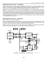
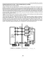
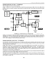
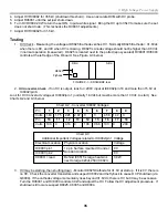
If the secondary power supply does not start, use Chart 7-1 to determine if an input to the D or G board is missing:
Refer to Figure 7-2 for the checkpoint locations on the boards.
Содержание KD-34XBR2 - 34" Hdtv Fd Trinitron Wega
Страница 77: ...74 RA 5A Chassis Board Layout ...
Страница 108: ...APPENDIX ...

