11
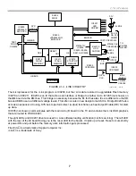
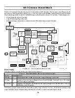
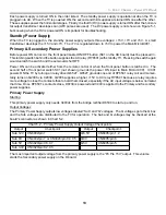
4. HA-3 Chassis Overall Block
Video Processing
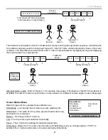
This TV will accept standard resolution inputs or high-resolution inputs.
Standard Resolution Input – A standard resolution signal could be selected from either analog tuner (NTSC) or
any composite video 1-4 input. However, this high resolution TV runs at a different horizontal frequency of
33.75kHz than what is input. To view a standard NTSC signal (480i) that runs at 15,734 Hz on this TV, the video
signal must be improved and the horizontal sync more than doubled. The improvement is performed in the DRC
circuits and the sync conversion and picture sizing is done in the MID circuitry. Both of these circuits are part of
the Q box.
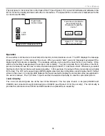
The Digital Reality Creation (DRC) Circuit analyzes each pixel of a line to add another line. Therefore, the DRC
circuit doubles the number of video lines of a standard NTSC signal. The DRC also doubles the horizontal sync
frequency before passing the signal onto the MID circuit on the same board.
The Multi Image Driver (MID) Circuit stores the lines and outputs the signal based on a new horizontal frequency
that matches the TV. At the higher frequency, the picture finishes before the scan. Blank lines are added as filler
by this MID stage before leaving the board.
The output of the Q box is a “Hi-Scan” (high-resolution) picture with separate H & V sync lines that are applied to
the Y/C CRT Drive IC3101 (A board). IC3101 converts the component video input into RGB for the CRT cathodes
and uses the sync input to lock the 60 Hz vertical oscillator and 33.75kHz horizontal oscillator.
High Resolution Input - Video inputs 5 and 6 are for Y, Pr and Pb component video signal types only. They can be
standard (480i) or high resolution (480p, 720p or 1080i) formats. The standard resolution signal must be switched
into the DRC circuit using the Main path (for up conversion), and the high-resolution signals must be sent into the
MID circuit using the Sub path (for sizing and sync conversion).
The DTV tuner signal is also fed into the MID circuit (Q box). The MID circuit selects one input (or two of the
inputs when in the Twin mode) and outputs a single “Hi Scan” picture with corrected sync to match the 33.75kHz
TV frequency. The component video that outputs the Q box is applied to Y/C CRT Drive IC3101 on the A board.
This IC level shifts (matrixes) the signal into an RGB output signal for each CRT cathode.
Deflection Stages
Chart 4-2 shows the two stages that feed the deflection yoke.
Chart 4-2 – HA-3 Chassis Deflection Stages – D board
Stage
Drive Source
Power Supply
Diagnostic Indication
Vertical Sweep
Y/C CRT Drive IC3101
+ 15Vdc from the Secondary PS (D Bd)
Blinks 4X
Horizontal Scan
Y/C CRT Drive IC3101
+135Vdc from the Secondary PS (D Bd)
Blinks 2X, 3X, or 7X
Vertical Sweep – Vertical drive signal comes from Y/C CRT Drive IC3101 synced to signal from the MID circuitry
on the QM board (in the Q box).
Horizontal Scan - Y/C CRT Drive IC3101 also develops H drive signal. The H drive is not only used to drive the
yoke, but also starts the HV Regulator stage.
Содержание KD-34XBR2 - 34" Hdtv Fd Trinitron Wega
Страница 77: ...74 RA 5A Chassis Board Layout ...
Страница 108: ...APPENDIX ...


