79
18. RA-5A Chassis - Power Supply Block
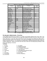
Chart 18-2 – Primary Power Supply Voltage Distribution G Bd to A Bd
Primary PS Output
Location
A board Destination
Output
Final Destination
Sub 6.5V (digital)
CN6104/pin 8,9
CN3015/pin 1,2
6.5Vdc
QM board CN7001/pin 1,2.
IC3002 Regulator
9V
QM board CN7001/pin 9.
Sub 9V
B board CN3020//pin C4,5
11Vdc
CN6104/pin 1
IC3005 Sw Regulator
9V
A board IC3021 5V Regulator
IC3003 Regulator
5V
QM board CN7001/pin 5.
5V
B board CN3020/pins C6,7
7V or 6.5V (analog)
CN6104/pin 2,3
IC3007 Sw Regulator
5V
AD board CN3012/pin 17,
Secondary PS
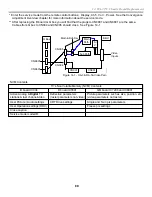
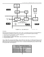
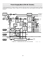
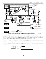
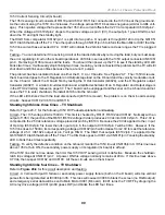
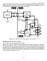
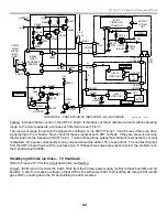
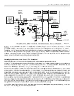
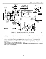
The secondary power supply starts after being enabled by the primary power supply, the Main Micro and the
surge relay. Figure 18-1 shows that the primary power supply makes VC1 to enable the secondary supply. The
second enable line comes from the Main Micro IC001 as a “Main Sw” HIGH voltage (CN6101/pin 9 = 5V) about ½
second after power ON. The third enable comes from the surge relay RY6002. If the RY6002 contacts close
before the capacitor in the Q6004/5 latch circuit charges, the latch does not activate and the V sense 2 line into
the secondary power supply is enabled. The secondary power supply may now power up because its V Sense
input is allowed to go HIGH.
All secondary PS outputs are fused, except the 19V and 135V lines. This power supply is connected to the D
(deflection) and K (audio) boards. The D board supplies 15V and 135V to the A board. The destinations for the
secondary power supply are listed in Chart 18-3.
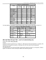
Chart 18-3 – Secondary Power Supply Voltage Distribution
Primary PS Output
Location
D board Destination
Output
Final Destination
IC8003 Vert Out
IC8004 Regulator
12Vdc
+15Vdc
CN6106/pin 1,3
Through to A board
+15Vdc
A board CN8004/pin 8,10
19Vdc
CN610
2
/pin 7,8
Through to K board
19Vdc
K board CN2104/pin 7,8
+22Vdc
CN6106/pin 4,6
IC8001/2 Conv Amps
H Drive, HV Conv
135Vdc
CN6106/pin 9
Through to A board
135Vdc
A board CN8006/pin 10
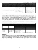
Power ON
The power ON sequence is similar to the HA-3 chassis (model KD34XBR2). Pressing the front panel or remote
control ON button activates power ON. Main Micro IC001 responds by energizing the AC relay (RY6001), which
powers the primary power supply. The primary power supply and Main Micro then turn ON the secondary power
supply to supply the remaining power to the TV set for operation. The sequence is summarized in Chart 18-4.
Содержание KD-34XBR2 - 34" Hdtv Fd Trinitron Wega
Страница 77: ...74 RA 5A Chassis Board Layout ...
Страница 108: ...APPENDIX ...

