15
5. HA-3 Chassis - Power ON Block
Output Voltages
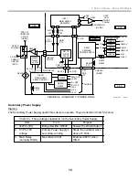
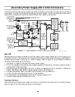
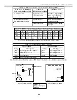
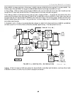
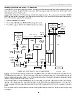
This secondary power supply produces the remainder of the low voltages to power the TV. These are listed in
Chart 5-4.
Chart 5-4 - Secondary Power Supply Load
Output
Protected
Destination
200V
Yes OCP
D Board - HV Converter power supply
135V
Yes. OVP, OCP
D board - Horizontal stages
Sample voltage returned for regulation
+24V
No
D board - Makes Main 12, Main 9 and
Main 5V used throughout the D board *
+15V
No
A board - Audio output stage
* see Chart 5-1 for source of voltages
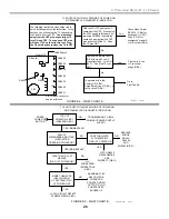
TV Power ON Sequence
1. Press the PWR ON button;
2. AC Relay energizes (RY6501);
3. Primary Power Supply starts (Q box is powered, Surge relay is energized);
4. Main Micro (B board) resets Q box (The Q box has flash memories for self initialization);
5. Q box acknowledges after initializing (TXD and RXD communications. See appendix);
6. Main Micro (B board) starts the Secondary Power Supply (Deflection and TV filaments start). The Secondary
power supply is started 100msec after power ON and independent of the Q box acknowledgment (step 5);
7. Main Micro (B board) retrieves information from the NVM ICs on the B communications bus and sends the
data to the appropriate TV operating ICs using the S communications bus;
8. HV starts after horizontal deflection operates (D board);
9. Shutdown circuitry is enabled (B board); and
10. IK circuitry (A board) adjusts the gain of the RGB amplifiers and unmutes the RGB signal to the CRT.
Содержание KD-34XBR2 - 34" Hdtv Fd Trinitron Wega
Страница 77: ...74 RA 5A Chassis Board Layout ...
Страница 108: ...APPENDIX ...

