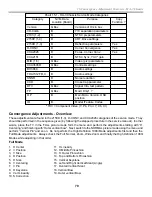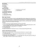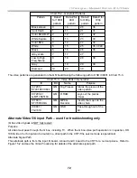
83
19. Projection TV RA-5A Chassis Power Supply Board Tests
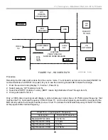
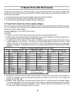
9. Place your scope at Q6009/Drain of the primary power supply. Gradually increase the Variac voltage. The
square Waveform 19-1 will start at 16Vac and gradually increase in amplitude. Make sure the waveform is flat
on the top and bottom and its Vp-p is at the same level as the DC voltage from main rectifier D6001. For
example at 20Vac, there is 60Vdc from D6001 and waveform should be 60Vp-p. Waveform 1 shows the
square shape at 20Vac input to the TV.
PM3394, FLUKE & PHILIPS
ch1: pkpk= 57.6 V
ch1: freq= 220kHz
CH1!10.0 V~ MTB1.00us ch1-
1
T
Waveform 19-1 - Primary PS Output – 20Vac
input
Name
Location
Voltage/div
Channel 1
IC6002
Output
Q6009/Drain
57Vp-p
Time base
1usec/div
Waveform frequency = 220kHz
G Board - RA-5a Chassis
Bottom view
CN6106
CN6101
CN6102
CN6104
PH6002
PH6005
Q6009
RY6001
Sec PS
IC6001
Q6003
1
1
Prim PS IC6002
Figure 19-1
10. Stop at each AC input level to recheck the output voltage and verify that almost no AC current is drawn. Only
the primary PS voltages in Chart 19-2 will output. The frequency of the primary oscillator should remain at
220kHz as the input voltage increases because the regulator circuit has been disabled (step 2).
11. Finally, test the regulating circuit by measuring the voltage across PH6005/pins 1-2 with the board powered
up. 0V = normal. 1.2V or higher means the regulating IC6107 is defective.
Running both the Primary and Secondary Power Supply
12. Unplug the AC and disconnect the DC voltage to the blocking diode.
13. Move the resistor and diode from IC6002/pins 1 and 7 to IC6001/pins 1 and 7.
14. Short Q6003/ base to emitter. This enables IC6001.
15. Move the short from across PH6005/pins 3-4 to PH6002/pins 3-4.
16. Place the scope probe at Q6007/Source to monitor the oscillator output.
17. Connect the DC power supply to the blocking diode that is soldered to IC6001/pin 7.
Chart 19-2 – Primary and Secondary Output Voltages at various input voltages
AC Input Voltage
20Vac
30Vac
50Vac
90Vac
120Vac
D6001 Output
60Vdc
87Vdc
146Vdc
254Vdc
336Vdc
Primary PS
CN6104/pin 1 (11V)
1.86Vdc
2.38Vdc
4.1Vdc
6.24Vdc
7.8Vdc
CN6104/pin 2 (7V)
1.1Vdc
1.55Vdc
2.7Vdc
4.6Vdc
5.8Vdc
CN6104/pin 8 (6.5V)
0.72Vdc
1.1Vdc
1.96Vdc
3.5Vdc
4.6Vdc
Secondary PS
CN6106/pin 9 (135V)
18.55Vdc
25.3Vdc
44.4Vdc
79Vdc
108Vdc
CN6106/pin 6 & 4 (+22V)
+3Vdc
+4.16Vdc
+7.6Vdc
+13.46Vdc
+18.3Vdc
CN6106/pin 3 & 1 (+15V)
+2Vdc
+2.8Vdc
+5Vdc
+8.8Vdc
+12Vdc
Содержание KD-34XBR2 - 34" Hdtv Fd Trinitron Wega
Страница 77: ...74 RA 5A Chassis Board Layout ...
Страница 108: ...APPENDIX ...


