


2-26 (E)
.
IM/HDCU1000 Series
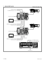
How to adjust using the VCS-700
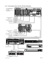
In the system with the MSU-900/950, CNU-700 or VCS-
700, the video output signal of HDCU1000/1080/1500 can
be checked on the waveform or vector monitor connected
to the WF A OUTPUT connector and the WF B OUTPUT
connector of the VCS-700.
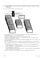
Connect the WF OUT connector of the VDA-64A/64B
board to the WF 1 connector of the VCS-700 and connect
the PIX OUT connector to the PIX 1 connector. Then
adjust the signal level using the color bar signal.
1.
Press the BARS button of the MSU-900/950, RCP-
750/751, etc., or press the ENC button of the WAVE-
FORM MONITOR buttons (or MONITOR SELECT
buttons) to display the color bars on the waveform or
vector monitor.
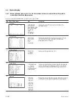
2.
Set the CONTROL switch of the VCS-700 to RESET.
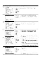
3.
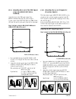
Adjust the color bars signal using the WFM 1 LEVEL
and WFM 1 CHROMA controls of the VCS-700 so
that it is within the specified level.
Measurement point : PIX OUT connector on the VCS-
700
Specification :
A = 100
±
1 IRE [for NTSC]
A = 700
±
7 mV p-p [for PAL]
(WFM 1 LEVEL control)
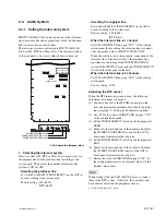
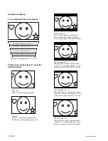
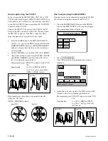
Each luminescent spot on the vector monitor must be
within the “
4
” range.
(WFM 1 CHROMA control)
R
M
G
B
C
Y
G
Y
L
R
M
G
C
Y
G
Y
L
B
[for NTSC]
[for PAL]
[for PAL]
[for NTSC]
A
A
Maintenance Menu
Adjusting
CAM SW
Setting
Auto
Setup
Exit
Lens
Adjusting
VCS
Adjusting
SD
Adjusting
SuperMotion
Setting
WF Level WF Chroma
Clear
Home
Low
Middle
High
100%
Chara-
cter on
VCS Monitor Level
Monitor
Level
1
1
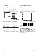
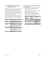
How to adjust using the MSU-900/950
The signal level can be adjusted by using the MSU-900/
950 instead of using the controls of the VCS-700.
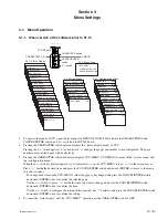
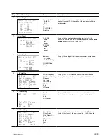
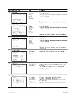
1.
Press the MAINTENANCE button of the MODE
block of the MSU-900/950 so that the button lights.
The maintenance menu is displayed.
2.
Press
[VCS|Adjusting]
.
The VCS monitor level adjustment item menu is
displayed.
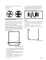
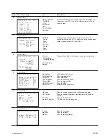
3.
Adjust the color bars signal of the WF Level and WF
Chroma so that it is within the specified level.
Measurement point : PIX OUT connector on the VCS-
700
Specification :
A = 100
±
1 IRE [for NTSC]
A = 700
±
7 mV p-p [for PAL]
(WF Level)
[for PAL]
[for NTSC]
A
A


