


2-18 (E)
.
IM/HDCU1000 Series
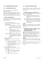
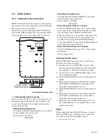
2. Setting the headset microphone
Set switch S4 (FRONT MIC) on the AU-302 board/
HDCU1000/1080 and switch S5 (FRONT MIC) on the
AU-303 board/HDCU1500 according to the type of headset
microphone to be connected to the front INCOM connector.
When using a carbon microphone : CARBON
(Sensitivity
_
20 dB, power is supplied.) (factory setting)
When using a electric condenser microphone : ECM
(Sensitivity
_
40 dB, power is supplied.)
When using a dynamic microphone : DYNAMIC
(Sensitivity
_
60 dB, power is not supplied.)
.
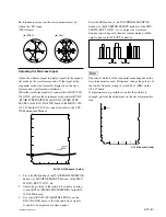
Adjusting the side tone level
From SIDE TONE on page “C05”
*
of the configuration
menu, adjust the side tone level of the headset to be
connected to the front INCOM connector according to
user’s preference.
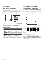
3. Setting the input level of the PGM audio signal
Set switches S502 (PGM1 IN) and S503 (PGM2 IN) on the
AVP-6 board to 0 dBu or
_
20 dBu according to each level
of audio 1 and 2 of the system.
Factory setting : 0 dBu
.
Selecting the PGM audio signal
From PGM-SEL on page “C05”
*
of the configuration
menu, set the PGM audio signal of the headset connected
to the front INCOM connector according to user’s
preference.
Selecting PGM 1 : PGM 1 (Factory setting)
Selecting mix of PGM 1 and PGM 2 : Mix
Selecting PGM 2 : PGM 2
.
Adjusting the mix amount of the PGM audio signal
From PGM1, 2 on page “C05”
*
of the configuration
menu, adjust the mix amount of the PGM audio signal of
the headset connected to the front INCOM connector
according to user’s preference.
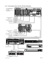
4. Selecting an intercom line to be connected to
the INCOM connector
Use the switch on the front panel to select the intercom line
to be connected to the INCOM connector on the front as
follows.
.
When connecting to the producer line
:
Set the INCOM SELECT switch to PROD.
.
When connecting to the engineer line
:
Set the INCOM SELECT switch to ENG.
.
When connecting only a camera
:
Set the INCOM SELECT switch to PRIV. When this
position is set, the intercom from outside is cut and the
system consists of the intercom and camera.
n
When INCOM-CH on page “C05”
*
of the configuration
menu is set to 1CH, the INCOM SELECT switches on the
front panel of HDCU1000/1080/1500 and the camera are
fixed to the producer line regardless of the setting.
*
: “C06” in software V1.10 or later
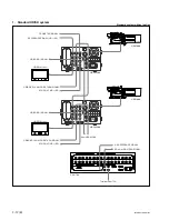
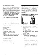
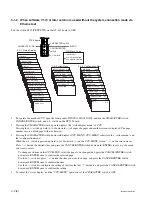
5. Setting the AVP-6 board switch
The flow of the switch setting on the AVP-6 board and the
intercom signals is as follows.
PROD
SHORT
OPEN
CAM
MAIN
CABLE
ALARM
INCOM
POWER
1
ENG
PGM
ON
MIC
OFF
PRIV
S4
AU-302 board
AU-303 board
S5
INCOM SELECT switch
HDCU1000/1080
HDCU1500
S502
S602,600
S603,601
0dB/–20dB
S503
0dB/–20dB
4W/RTS/
Clear-Com
4W/RTS/
Clear-Com
PRIV(Front panel)
PRIV(Front panel)
ENG/PROD (Camera side)
2CH/1CH (Menu)
ENG/PROD (Camera side)
2CH/1CH (Menu)
4
X
5
@/
8
7
5
!.
!\
3
2
1
!]
Y
G
X
Y
G
X
Y
X
Y
G
X
Y
Program line 1
X
Y
G
Program line 2
System intercom
Talk
Producer line
Receive
Talk
Receive
INCOM/TALLY/PGM
connector on the rear panel
3. Select the
PGM audio input level
PGM 1
PGM 2
INCOM 2
INCOM 1
3. Set the mix amout of
PGM audio signal
(Menu)
INCOM SELECT switch
on board panel
4. Setting for the
INCOM connector
on the front panel
1. Select the input 4W/RTS/
Clear-Com
Engineer line
To the INCOM connector on the front panel
!'
9
!/
@=
PGM 1/PGM 2
(Menu)


