


2-20 (E)
.
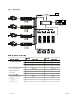
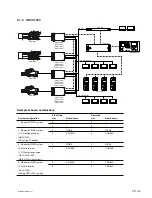
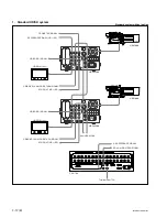
IM/HDCU1000 Series
2-4. Systems
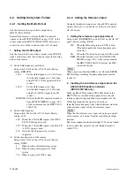
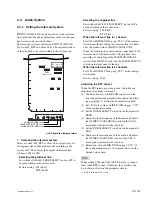
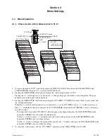
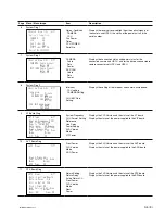
2-4-1. Setting the Tally System
HDCU1000/1080/1500 supports the red tally and the green
tally. It also supports the MAKING CONTACT and
supplying power (24 V/TTL). Set the switches on the
AVP-6 board according to the system used as follows :
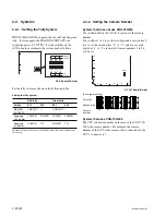
AVP-6 board (A side)
Set the tally system as shown in the following table.
Setting the tally system
Red tally
Green tally
Switch
S11
S12
S21
S22
MAKING
CONTACT
_
CONTACT
_
CONTACT
Supplying
POWER
POWER
POWER
POWER
24 V power
Supplying
POWER
TTL
POWER
TTL
5 V power
Switches S11 and S12 are set to CONTACT when the unit is shipped from
the factory.
EF
G
H
J
S12
S11
S22
S32
S21
S31
R-TALLY
G-TALLY
U-TALLY
POWER
CONTACT
POWER
TTL
1
2
3
4
5
6
0
7
8
50
5
1
2
3
4
5
6
1
7
8
61
6
1
2
3
4
5
6
2
7
8
72
7
1
2
3
4
5
6
3
7
8
83
8
1
2
3
4
5
6
4
7
8
94
9
(Example of setting)
First digit
Second digit
Camera
number
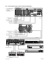
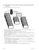
2-4-2. Setting the Camera Number
System that does not use CNU-700/500
Use switch S409 on the AT-167 board to set the camera
number.
Use switches 1 to 4 to set the first digit and use switches 5
to 8 to set the second digit. “0” to “f” can be set as each
digit, but “a” to “f” are invalid. Camera numbers 1 to 96
can be set.
AT-167 board (A side)
System that uses CNU-700/500
The CCU connector number on the rear of the CNU-700/
500 is the camera number. For example, the camera
number of the CCU video camera that is connected to the
CCU 1 connector is 1.
AB
C
D
1
2
3
4
5
S409


