


2-19 (E)
.
IM/HDCU1000 Series
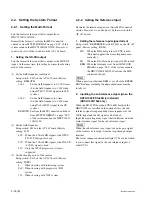
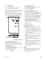
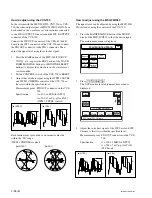
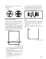
Setting the Microphone Output Level
AVP-6 board (A side)
Select the microphone output signal level (0 dB,
_
20 dBu)
from the MIC 1, 2 connector on the rear using the switches
on the AVP-6 board.
.
Setting the output level of MIC 1 :
Switch S500 (MIC 1 OUT LEVEL)
.
Setting the output level of MIC 2 :
Switch S501 (MIC 2 OUT LEVEL)
.
Factory setting : 0 dBu (both S500 and S501)
The microphone output signal level from the MIC 1, 2
connector on the rear can be adjusted using the volume on
the AVP-6 board.
.
Setting the output level of MIC 1 :
1
RV500 (MIC 1 OUT LEVEL)
.
Setting the output level of MIC 2 :
1
RV501 (MIC 2 OUT LEVEL)
*
: “C05” in software V1.10 or later
EF
G
H
J
RV501
RV500
S501
S500
1 1
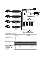
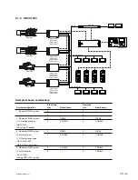
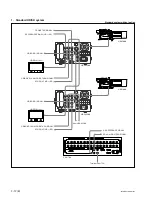
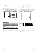
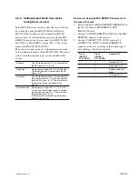
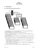
2-3-2. Setting the Microphone
HDCU1000/1080/1500 can output the two independent
microphone lines (MIC 1, MIC 2) of video camera
HDC1000 series as it receives these MIC signals.
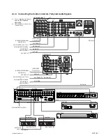
Controlling the Microphone Input Gain Using the
Remote Control
HDCU1000/1080/1500 can adjust the input gain of the
MIC connector of camera HDC1000 series using the
remote control in the range of 60 dB to 20 dB in 10 dB
steps using either of the following methods.
1. Adjusting the microphone input gain to be set
from MENU
When the MIC REMOTE connector on the rear panel is
connected to nothing or the levels of pin-8 (MIC 1) and
pin-15 (MIC 2) of the MIC REMOTE connector are High,
the microphone input gain can be adjusted from CHU MIC
GAIN on page “C04”
*
of the configuration menu.
Factory setting : (60 dB)
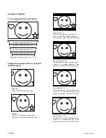
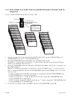
2. Adjusting the microphone input gain using
the MIC REMOTE connector
Set the microphone input gain control to ON or OFF with
pin-8 and pin-15 of the MIC REMOTE connector on the
rear as shown below. The input gain can be controlled via
pin-5, pin-6 and pin-7 as shown below.
Setting the microphone input control of the video camera
Pin No.
Microphone connector
8
15
MIC IN CH-1
MIC IN CH-2
L
L
ON
ON
L
H
ON
OFF
H
L
OFF
ON
H
H
Internal setup (Menu page “C04”
*
)
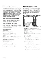
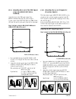
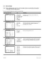
Setting the microphone input gain of the video camera
Pin No.
Input gain
7
6
5
60 dB
H
H
H
50 dB
L
H
H
40 dB
H
L (H)
H (L)
30 dB
L
L (H)
H (L)
20 dB
H
H (L)
L (H)
H :
+
5 V or OPEN
L : GND
Input resistance : Pulled-up 100 k
Z
+
5 V
The setup for the HDCU-700A mode is shown in parenthesis ( ) :
S406-2/AT-167
→
ON
3. Adjusting the MIC signal phase
When the microphone signal phase is ahead of the video
signal phase to be used, adjust the amount of audio delay
from MIC OUT DELAY on page “C04”
*
of the configura-
tion menu.
Factory setting : 0 Fs


