


1-26 (E)
.
IM/HDCU1000 Series
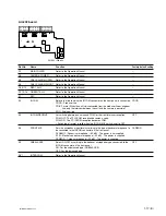
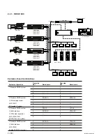
1-9. Installation Position of the Option
Board
The following optional boards can be available for HDCU.
Use different slots for each board and set the switches
respectively.
For the details, refer to Section 2-1, “System Connection”.
Model
Board
Board
(slot in
(slot in
the front)
the rear)
HKCU1001
EN-159A
VDA-64A
SD Analog Interface Unit
HKCU1003
EN-159B
VDA-64A
MULTI Interface Unit
*
VDA-64B
VDA-64C
HKCU1005
DRX-5
HIF-26
SDI Output Expansion Unit
*
: HKCU1003 is the option board for HDCU1000. It is not used for
HDCU1080.
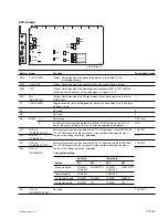
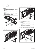
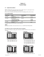
5.
Attach the fuse in the reverse order.
n
A spring is already attached in the fuse holder. When
attaching a new fuse, rotate the flat-blade screwdriver
in the direction of arrow C (by about 90
d
) while
pressing it in the direction of arrow B to lock the fuse
holder.
Fuse holder
B
C
Flat-blade
screwdriver
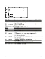
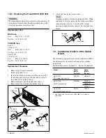
1-8-2. Replacing the Fuse (HDCU1000/1080)
w
The components marked
!
are critical to safe operation. If
you replace with parts other than the specified ones, a fire
or electric shock may result from that.
Replacement Part
MAIN fuse
Part :
Fuse (3.15 A, 250 V)
Part No. :
!
1-576-230-51
CAMERA fuse
For UC
100 to 120 V
Part :
Fuse ( 6.3 A, 250 V)
Part No. :
!
1-576-233-51
For CE, CN
220 to 240 V
Part :
Fuse (4 A, 250 V)
Part No. :
!
1-576-231-51
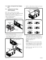
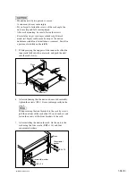
Replacement Procedure
1.
Remove the PS panel assembly.
(Refer to Section 1-8-1.)
2.
Insert a flat-blade screwdriver into the groove of the
fuse holder, and rotate it in the direction of arrow A
(by about 90
d
) to unlock. (Fig. 1)
3.
Remove the fuse with the fuse holder. (Fig. 2)
4.
Remove the fuse from the fuse holder. (Fig. 3)
Fig.1
Fig.2
Fig.3
MAIN fuse
CAMERA fuse
A
Flat-blade
screwdriver
Fuse holder
Fuse holder
Fuse holder
Groove
Fuse
Two fuse holders


