6-2
FVS-1000 MMP1
+12 V
+3.3 V
–5 V
+5 V
E2
+3.3 V -2
Extension board (EX-632)
Check terminals
Front cover
Extension board (EX-632)
SHUTDOWN
button
SYSTEM
indicator
POWER
indicator
_
5 V
+
12 V B
+
12 V A
+
5 V A
+
5 V B
+
3 V
Power switch
Power supply unit
Potentiometers
GND E
+
5 V A
+
12 V B
+
12 V A
GND A
Check terminals
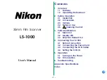
6-2. Power Supply Unit Adjustment
6-2-1. Power Supply Unit
The FVS-1000 system has two power supply units; the
upper power supply unit mainly supplies power to the
ninth board from the right of the processor to the left
board, while the lower power supply unit mainly supplies
power from the right board of the processor to the eighth
board.
6-2. Power Supply Unit Adjustment
Voltage
Specification
Check terminal
Adjustment potentiometer
+
12 V
+
12.00
±
0.05 V dc
EX-632 board
Power supply unit
+
12 V
↔
GND (E2)
1+
12 VA
+
5 V
+
5.00
±
0.05 V dc
EX-632 board
Power supply unit
+
5 V
↔
GND (E2)
1+
5 VB
+3.3 V
+3.30
+
0.05
Vdc
EX-632 board
Power supply unit
_
0.00
+
3.3 V
↔
GND (E2)
1+
3 V
_
5 V
_
5.00
±
0.05 Vdc
EX-632 board
Power supply unit
_
5 V
↔
GND (E2)
1_
5 V
+
5 V (A)
+
5.10
±
0.05 Vdc
Upper power supply unit
Power supply unit
+
5 VA
↔
GND E
1+
5 VA
+
12 V (B)
+
12.00
±
0.05 Vdc
Upper power supply unit
Power supply unit
+
12 VB
↔
GND E
1+
12 VB
Eighth board from the right (SY-256)
Upper power
supply unit
Lower power
supply unit
From the lower
power supply unit
From the upper
power supply unit
A. Checking/adjusting the voltage of the upper
power supply unit
Measuring instruments: Digital voltmeter
Tool:
Extension board EX-632
(For front board)
Preparations
1.
Open the door at the bottom of the unit, and turn OFF
the breaker and two power supply switches.
2.
Loosen the four screws, and remove the front cover of
the processor.
3.
Insert the extension board EX-632 into DCP1 slot
(fourth from the left) along the guide rail.
4.
Turn ON the breaker and two power supply switches.
Содержание BKFV-100/1
Страница 4: ......
Страница 10: ......
Страница 68: ......
Страница 72: ...2 4 FVS 1000 MMP1 1 1 1 1 1 7 6 8 9 1 1 5 4 2 3 Rear side 2 3 Location of Main Parts FVS T1000 Rear panel ...
Страница 78: ...2 10 FVS 1000 MMP1 4 5 6 8 8 9 7 3 2 1 Front side 2 3 4 Location of Sensors 2 3 Location of Main Parts ...
Страница 130: ......
Страница 194: ......
Страница 202: ......
Страница 248: ...7 4 FVS 1000 MMP1 O A 8321 649 E FILTER ASSY BOX S 1 758 295 11 IR UV CUT FILTER S 1 517 872 11 LAMP WITH PLASTIC CASE ...
Страница 250: ......
Страница 256: ......
Страница 258: ...Printed in Japan Sony Corporation 2001 12 08 B P Company 1999 FVS T1000 UC FVS P1000 SY E 3 202 167 04 ...