background image

2-57

FVS-1000 MMP1

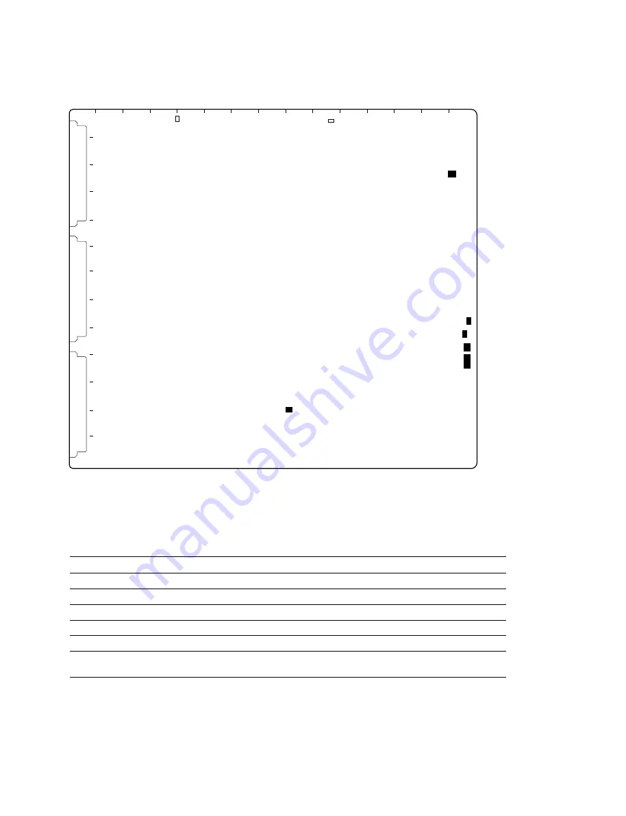
2-11-17. DP-345 Board (BKFV-300)

Switches

n

Do not change the setting of the switch described as “Factory use only”.

Ref.No.

Address

Name

Function

Factory setting

S3500

(R-8)

DP reset switch

Initialize the DP board

S3900

(R-9)

DSP reset switch

Initialize the DSP

S3600

(J-11)

1 to 2: Factory use only

All bits OFF

S3700

(R-10)

1 to 8: Factory use only

All bits OFF

S3701

(R-9)

1 to 4: Factory use only

All bits OFF

S3702

(R-3)

1 to 4: Factory use only

(b1, b2, b3, b4) = (L, H, L, H)
L: OFF  H: ON

S3500

S3702

S3600

A

B

C

D

E

F

G

H

J

K

L

M

N

P

R

1

2

3

4

5

6

7

8

9

10

11

12

13

S3900

S3701

S3700

DP-345 BOARD (A SIDE)

2-11. Function of Switches/LEDs on the Board

Содержание BKFV-100/1

Страница 1: ...PROCESSOR FVS P1000 MULTI RESOLUTION TELECINE BKFV 100 1 TELECINE HDTV PROCESSING BOARDS TELECINE SDTV PROCESSING BOARDS BKFV 200 TELECINE OPTICAL KIT BKFV 410 TELECINE LOG DATA PROCESSOR BKFV 300 TELECINE 16 mm FILM ADAPTOR KIT BKFV 400 1 TELECINE MOUNTED SLIDE KIT BKFV 420 TELECINE FILM SOUND PROCESSOR BKFV 500 ...

Страница 2: ...n nur von Personen ausgeführt werden die eine spezielle Befähigung dazu besitzen AVERTISSEMENT Ce manual est destiné uniquement aux personnes compétentes en charge de l entretien Afin de réduire les risques de décharge électrique d incendie ou de blessure n effectuer que les réparations indiquées dans le mode d emploi à moins d être qualifié pour en effectuer d autres Pour toute réparation faire a...

Страница 3: ...t moment dat u het apparaat bij einde levensduur afdankt Gooi de batterij niet weg maar lever hem in als KCA Bij dit produkt zijn batterijen geleverd Wanneer deze leeg zijn moet u ze niet weggooien maar inleveren als KCA Für Kunden in Deutschland Entsorgungshinweis Bitte werfen Sie nur entladene Batterien in die Sammelboxen beim Handel oder den Kommunen Entladen sind Batterien in der Regel dann we...

Страница 4: ......

Страница 5: ...0 1 31 1 11 2 BKFV 400 1 1 36 1 11 3 BKFV 410 1 39 1 11 4 BKFV 420 1 40 1 11 5 BKFV 500 1 42 2 Service Overview 2 1 Operating Conditions 2 1 2 2 Supplied Accessories 2 1 2 3 Location of Main Parts 2 1 2 3 1 Location of Main Blocks 2 1 2 3 2 Location of Boards 2 2 2 3 3 Location of Main Mechanical Parts 2 9 2 3 4 Location of Sensors 2 10 2 4 Film Threading 2 12 2 5 Connecting Connector Cable 2 13 2...

Страница 6: ... 2 56 2 11 17 DP 345 Board BKFV 300 2 57 2 11 18 DIF 120 Board BKFV 300 2 58 2 11 19 CN 2243 Board BKFV 300 2 59 2 11 20 AU 278 Board BKFV 500 2 60 2 11 21 PRE 46 Board BKFV 500 2 61 3 Periodic Check and Maintenance 3 1 Periodic Inspection List 3 1 3 1 1 Telecine Main Unit FVS T1000 3 1 3 1 2 Film Sound Processor BKFV 500 3 2 3 2 Cleaning the Running System 3 2 3 2 1 Cleaning the Gate Base 35 16 A...

Страница 7: ...um Top and Bottom 3 34 4 Replacement of Main Parts 4 1 General Information on Parts Replacement 4 1 4 2 Replacing the Pad Assembly 4 2 4 3 Replacing the PT Assembly 4 4 4 4 Replacing the Reel Assembly 4 6 4 5 Replacing the Tension Regulator Assembly 4 10 4 6 Replacing the S AU Assembly 4 18 4 7 Replacing the Guide Roller Assembly 4 19 4 8 Replacing the Guide Plate Assembly 4 23 4 9 Replacing the T...

Страница 8: ...6 Lamp House Adjustment 6 17 6 6 1 LC 35 Board Adjustment 6 17 6 6 2 35 mm Integrating Sphere Offset Gain Adjustment 6 21 6 6 3 16 mm 8P Integrating Sphere Adjustment 6 24 6 7 Processor Adjustment Including BKFV 200 6 27 6 7 1 ADC 36 Board Adjustment 6 27 6 7 2 SY 256 Board Adjustment 6 28 6 7 3 RX 45 Board Adjustment 6 29 6 7 4 TX 67 Board Adjustment 6 30 6 8 BKFV 100 Adjustment 6 31 6 8 1 OPM 28...

Страница 9: ...FVS 1000 MMP1 5 8 Block Diagrams Processor Block 8 1 Servo Block 8 2 Power Supply Block For J 8 3 Power Supply Block For UC 8 4 Power Supply Block For EK 8 5 ...

Страница 10: ......

Страница 11: ... Processor BKFV 500 Related manuals Beside this Maintenance Manual Part 1 the following manuals are available for the FVS 1000 FVS 1000 System Operation Manual Supplied with FVS T1000 BKFV 300 500 Part number 3 866 844 01 This manual describes the application and operation FVS 1000 System Maintenance Manual Part 2 Volume 1 Available on request Part number 9 967 822 XX This manual is intended for u...

Страница 12: ...enter FVS 1000 System Maintenance Manual Part 3 Volume 3 Available on request Part number 9 955 251 XX This manual describes the schematic diagrams If this manual is required please contact your local Sony Sales Office Service Center Semiconductor Pin Assignments CD ROM Available on request This Semiconductor Pin Assignments CD ROM allows you to search for semiconductors used in B P Company equipm...

Страница 13: ...t is easy to move Supplied accessaries FVS T1000 Description Amount Operation manual x 1 Maintenance manual part 1 x 1 Knob for spool x 2 Control panel Control panel assembly x 1 Rack angle x 2 Screw B5 x 10 x 4 Screw PSW4 x 10 x 4 Lens 35 mm conversion lens x 1 Master zoom lens x 1 OPS mirror OPS assembly x 1 Screw PSW3 x 6 x 4 Air blow assembly Air blow assembly x 1 Connecting elbow assembly x 1...

Страница 14: ...s a danger of death or severe injury with it tumbled Operating temperature 10 dC to 35 dC Recommended temperature range 20 dC to 25 dC Operating humidity 20 to 90 no dew condensation Evenness of floor 5 mm or less Height of ceiling 500 mm or more from the top of the system Strength of floor 12 kN m2 1200 kgf m2 or more 6 kN point 600 kgf point or more n The pressure per 1 point is the sum of the p...

Страница 15: ...on space taking ventilation and servicing into consideration Leave a space where a person can pass at the left or right side of the FV S 1000 and a space of 500 mm or more at the top of the FVS 1000 1 4 Dimensions and Weight 1 5 Installation Space Unit mm 780 1173 1839 5 1852 5 1200 800 700 800 700 700 500 mm or more Leave a space where a person can pass at either of Unit mm Ceiling ...

Страница 16: ...ir from the pipe arrangement for supplying the high pressure air check the pressure flux and quality of the air then satisfy the above specifications using a regulator or filter and then connect When there is no pipe arrangement to supply the stable air it is recommended to use the oil free compressor equipped with a tank n If the air of which the pressure is more than the above specified value is...

Страница 17: ...rews When installing the FVS 1000 be careful not to forget tightening the screws Put away the unneces sary screws and do not leave the screws incompletely tightened If the parts or screws fall during the operation there is a possibility of causing some trouble or mis operation Screws must be tightened with the following tightening torque Hexagonal screws with hole M3 98 x 10 _2 N m 10 0 kgf cm Hex...

Страница 18: ...install 2 Installation 3 Connection of the power supply cord 5 Installation of the air blow assembly 6 Removing the screws used during transportation 7 Prevention of falling down 8 Installation of the control panel 9 Installation of the OPS assembly 10 Installation of the FVS P1000 and BKFV 100 200 11 Turning on the power 12 Installation of the lens 13 Confirmation of the operation Completion 4 Op...

Страница 19: ...he clearance from the caster to the floor becomes 50 mm m Use the handlifter of its two claws width is 500 mm or less Insert the claw to the center position between the casters Place a rubber sheet etc at the part where the claws and the door of the unit contact When a handlifter is not available lift up the unit in the following procedure 1 Place the wooden plates of their thickness are 20 mm und...

Страница 20: ... the unit and the Non vib mounts assemblies with sup plied eight screws C6 x 10 6 Lower the handlifter and pull from the unit 7 Securely tighten the relational plate and the Non vib mounts assembly n Never tighten the screws excessively when the clearance between the relational plate and the Non vib mounts assembly is broad Again lift up the unit with the handlifter then securely tighten the screw...

Страница 21: ...cher einzufügen damit sich bei einer Funktionsstörung die Stromversorgung zum Gerät jederzeit unterbrechen läßt AVERTISSEMENT AVERTISSEMENT AVERTISSEMENT AVERTISSEMENT AVERTISSEMENT Lors de l installation incorporez un interrupteur dans le fil électrique fixé près de l appareil pour qu on puisse couper l alimentation en cas d anomalie m Use the specified power supply cord If the power supply cord ...

Страница 22: ...ere is a danger of an electrical shock 1 Remove nine screws then remove the rear panel 2 Remove the two screws and open the sub panel 3 Prop up the sub panel with a support 4 Remove the two screws and remove the RM board bracket B4 x 8 Rear panel B4 x 8 B3 x 6 B3 x 6 PSW4 x 8 PSW4 x 8 RM board bracket Rod Sub panel ...

Страница 23: ...e specified power supply cable to the terminal table as shown in the figure 11 Attach the cover to the terminal table 12 Fix the power supply panel to the unit with two screws 13 Attach the power supply cover RM board bracket and rear panel to the unit in the reverse order of above steps n Pull out the power supply cord through the notch of the rear panel PSW4 x 8 Power supply panel Nut Nut Pipe P...

Страница 24: ...embly 2 Remove the two screws and remove the panel When removing the screw on the right side of the panel be sure to use a L shaped wrench 3 Insert the waveform monitor case and fix it with four screws 1 10 Installation Procedure B3 x 6 CAP3 x 6 Panel Move panel assembly B4 x 8 B4 x 8 Waveform monitor case Power supply cable ...

Страница 25: ...wer supply cable out of the unit and connect it to the waveform monitor 5 Insert the waveform monitor in the waveform monitor case 6 Remove the eighteen screws and remove the rear panel Middle 7 Fix the waveform monitor to the waveform monitor case with two screws 8 Attach the rear panel Middle 1 10 Installation Procedure ...

Страница 26: ... B5 x 8 B5 x 8 Lower console 1 Open the lower door 2 Remove the six screws and remove the front panel 3 Draw the power supply cable out of the unit and connect it to the optional unit to be installed 4 Fix the optional unit to the console with four screws 1 10 Installation Procedure ...

Страница 27: ...embly 1 Loosen the four screws of the rear panel 2 Hang the air blow assembly on the four screws loosened in step 1 with passing the screws through the holes on the four corners of the air blow assembly 3 Remove the four screws then remove the air filter cover from the air blow assembly Air filter cover Air blow assembly B3 x 6 B4 x 8 B4 x 8 B3 x 6 ...

Страница 28: ...r panel with the two screws B3 x 6 n Put the harness inside as much as possible 7 Insert the tube ø8 to the elbow one touch joint of the air blow assembly n Insert the tube completely then confirm that it does not come out by pulling slightly 8 Insert the connecting elbow to the bulkhead union n Insert the connecting elbow completely then confirm that it does not come out by pulling slightly B3 x ...

Страница 29: ...ped Do not supply the outside air before completing the installation 10 Insert the drain assembly to the drain one touch joint of the air blow assembly w Be sure to connect the tube with the drain If no tube is connected there is a case that the liquid is scattered then enters eyes or stains clothes When the liquid enters eyes clean the eyes in the clean water immediately then consult a physician ...

Страница 30: ...ng the regulator knob so that the indicator of the manometer may point to the following value Specification 0 1 Mpa 1 kgf cm2 4 Release the red button of the electromagnetic valve Push the regulator knob to be locked 5 Stop supplying the outside air 12 Install the air filter cover removed in step 3 n Be careful not to insert the harness between the air blow assembly and the air filter cover Electr...

Страница 31: ... BP screws for transportation in the drawer of the unit 7 Prevention of falling down To prevent the FVS 1000 from falling down by an earthquake etc it is recommended to fix the FVS 1000 w To prevent the FVS 1000 from falling down or moving be sure to fix the FVS 1000 to the ceiling which has the enough strength using a chain etc Fixing to the ceiling or pillar using eyebolt On the top of the FVS 1...

Страница 32: ...4 x 10 4 Place the control panel on the hinges and fix with the four screws B5 x 10 provided Move the hinges in the arrow direction and attach them 5 Connect the connector and the pin jack at the rear side of the control panel then fix the harnesses with the harness band Lock screw Hinge Lock screw Hinge B5 x 8 B5 x 8 B5 x 8 PSW4 x 10 PSW4 x 10 PSW4 x 10 PSW4 x 10 B5 x 8 Control panel Rack angle R...

Страница 33: ...mbly and OPS support plate then fix it with the supplied four screws M3 x 6 3 Connect the connector of the base plate with CN1 on the SE 515 board 4 Adjust the hole at the rear of the OPS cover to the OPS support push in the OPS support completely and install to the base plate Control panel OPS cover OPS assembly OPS support SE 515 board CN1 OPS support plate OPS support plate PSW3 x 6 PSW3 x 6 Co...

Страница 34: ...the lower front door of the FVS 1000 2 Pull out the flat cable and the coaxial cable fixed to the front cover 3 Loosen four screws with stopper then remove the front cover Clip plate Screw with stopper Screw with stopper Front cover Screw with stopper PSW3 x 6 Handle Flat cable Coaxial cables Door Screw with stopper ...

Страница 35: ...ely RK5 x 14 9 Push in the processor assembly completely n Firmly push in the two power connectors of the processor assembly to the connectors of the unit until they connect 10 Connect the connector CN3 rear of the processor assembly from the rear of the unit n Never mistake the connector to connect If misconnect the unit will not make operations by system error 11 Secure the processor assembly wi...

Страница 36: ...N402 702 and 120 connectors on the ADC 36 board 15 Install the front cover then tighten four screws n Pull out the flat cable and the coaxial cables connected with the processor boards through the notch of the front panel then fix with the clip plate and two screws PSW3 x 6 Rear side 1 Loosen the two screws with stopper then remove the cover PSW3 x 6 CN402 CN702 CN102 CN6027 Clip plate Processor b...

Страница 37: ...the processor boards attach the rear shield to the processor assembly with sup plied 11 screws for UC CE model only n The processor assembly can not be pulled out from the unit when the rear shield is attached When pulling out the processor assembly from the unit remove the rear shield 5 Connect the cable to the connector of the processor board 6 Attach the duct cover to the rear of the unit using...

Страница 38: ...e external switchboard 2 Open the lower front door of the FVS 1000 then turn on the breaker and the power switch Reference Once the power is turned on unless the power switch is turned off ON OFF of the power is possible by only switching the breaker with the lower door closed Power switch Breaker ...

Страница 39: ...the conversion lens Tighten the ring of the conversion lens first before proceeding to tighten the ring of the master zoom lens 3 Connect the cable of 35 mm conversion lens with the connector of the master zoom lens Reference Reference Reference Reference Reference Removing the Conversion Lens Loosen the ring of the master zoom lens first before proceeding to loosen the ring of the conversion lens...

Страница 40: ...crew a B3 x 6 then loosen the screw b B3 x 6 and then open the cover on the rear door of the FVS 1000 in the direction of arrow 3 Push the LENS EXCHANGE button 4 Confirm that the lamp changes from flashing to lighting then open the rear door 5 Release the lock then pull out the imager movement table assembly 6 Turn the lens mount lever in the direction of arrow then remove the protection cap from ...

Страница 41: ...ap is removed to the imager then turn the mount lever in the direction of arrow as shown in the following figure to fix 8 Connect the lens control cable with the connector of the imager movement table assembly 9 Insert the imager movement table assembly then tighten the lock 10 Close the rear door 11 Close the door opened in the step 2 then fix with the two screws Imager movement table assembly Lo...

Страница 42: ... 50 525 525 SD1 SD2 60 60 625 625 50 50 48 48 OUTPUT DESTINATION HOUR MIN SEC FRAME SYSTEM ERROR ALARM WARNING RESET PRESET SELECT REW REV STOP PLAY FF STEP REV STANDBY SEARCH MARK IN MENU HOME CMD1 CMD2 STEP FWD VARI LOCKED PLAY field MODE 4 3 2 1 FUNCTION EXECUTE SOURCE MEMORY MODE MODE KEY INHIBIT ON OFF MASTER PAN IRIS RED TILT FOCUS GREEN ZOOM ZOOM BLUE ROTATION SHUTTLE JOG READY REVERSE FORW...

Страница 43: ...89 board Applied at Ver 2 0 Attaching the insulation board to the extension board EX 632 for the front Make sure that at least these items mentioned on the above have been completed beforehand When BKFV 300 is installed to the unit with the following serial numbers the updating described below are necessary Affected serial numbers FVS T1000 10003 10302 10303 10304 10401 10402 10403 10404 10405 105...

Страница 44: ...en the lower front door of the FVS 1000 2 Pull out the flat cable and the coaxial cable fixed to the front cover 3 Loosen four screws with stopper then remove the front cover Clip plate Screw with stopper Screw with stopper Front cover Screw with stopper PSW3 x 6 Handle Flat cable Coaxial cables Door Screw with stopper 1 11 Installation of Optional Units ...

Страница 45: ...ssor board completely until the connector is connected 7 Connect the three coaxial cables with the CN402 702 and 120 connectors on the ADC 36 board 8 Connect the flat cable with the CN6027 connector on the MY 89 board 9 Install the front cover then tighten four screws n Pull out the flat cable and the coaxial cables connected with the processor boards through the notch of the front panel then fix ...

Страница 46: ...anel remove itself 4 Insert the DIF 120 board along with the 3rd guide rail from the left Use the 3rd and 4th slot for the panel 5 Tighten the upper and lower knobs one after the other several times then insert the connector completely until the connector is connected n Be sure to tighten the two screws one after the other If one screw is tightened completely first there is a possibility of damagi...

Страница 47: ...nit when the rear shield is attached When pulling out the processor assembly from the unit remove the rear shield 7 Connect the cable to the connector of the processor board 8 Attach the duct cover to the rear of the unit using supplied four screws for UC CE model only Rear shield for UC CE model only Screws Screws Screw Screws B4 x 6 Duct cover for UC CE model only B4 x 6 Cable 1 11 Installation ...

Страница 48: ...m zoom lens with the lens attached to the FVS 1000 As for the installation replacement procedures refer to step 12 Installation of lenses in Installation Procedure of Section 1 10 2 Gate Integrating Sphere 16 Assembly Replacement Rotate the two one touch screws 90 degrees in counterclockwise direction by hand and then replace the gate integrating sphere 35 assembly of the FVS 1000 with the gate in...

Страница 49: ...adjusted with other FVS 1000 When installing the pad assembly which is using with other FVS 1000 it is necessary to perform the pad roller clearance adjustment As for the detailed installing procedures refer to Section 3 4 5 Rotate the two one touch screws in counterclockwise direction by hand and then replace the 35S 35T pad assembly with 16S 16T pad assembly Refer to Section 4 2 Replacing the Pa...

Страница 50: ...ve the core retainer 35 assemblies on both S side and T side reel tables and then replace it with core retainer 16 assemblies 6 Electrical Adjustment When the BKFV 400 1 is purchased simultaneously with the FVS T1000 and FVS P1000 these electrical adjustments are already finished at the factory Therefore these adjustments are not neces sary to perform When only the BKFV 400 1 is purchased be sure ...

Страница 51: ... Conversion Lens Installation Replacement Procedures 1 Conversion Lens Replacement Replace the 35 mm conversion lens of the FVS 1000 with 35 mm aspect conversion lens As for the details of installation replacement procedures refer to step 12 Installation of the Lenses of Section 1 10 Installation Procedures n After replacement if the generating line is slanting notably perform the Section 6 11 1 A...

Страница 52: ...on Procedures 2 Integrating Sphere Replacement Removing m When removing the integrating sphere be sure to turn OFF the power of the FVS 1000 When replacing the 16 mm standard integrating sphere which was installed to the FVS 1000 for 16 mm use with 8P integrating sphere the gate base assembly to install the integrating sphere should also be replaced together Describes the replacement procedures in...

Страница 53: ... These adjustments should be performed when the integrating sphere is attached in the unit for the first time the mounted circuit board inside the integrating sphere is replaced or the lamp is replaced 3 Slide Adaptor Installation Align the two pins of the gate base 35 assembly with two holes of slide adaptor and place the slide adaptor on the gate base 35 assembly 1 11 Installation of Optional Un...

Страница 54: ...g is not required When updating is required please contact your local Sony Sales Office Service Center Updating Items Blank panel replacement Blank panel 1 3 617 421 03 1 pc Blank panel 3 628 101 02 1 pc Blank panel 5 3 623 820 04 1pc If BKFV 300 is already installed this part in not necessary Board position label Board position label F 3 617 622 03 1 pc Board position label R 3 617 621 03 1 pc La...

Страница 55: ...lation of the AU 278 board 1 Removal of the FTP panel 4 Connection of the inter lock harness 7 Adjustment 5 Installation of the analog audio assembly 6 Guide roller height adjustment 10 Installation of the caution label 8 Installation of the FTP panel and S electrode of ionizer 9 Installation of the audio cover and handle 1 11 Installation of Optional Units ...

Страница 56: ...ssembly Refer to Section 4 6 2 Remove the two screws and remove the S guide installation panel from the S AU assembly 3 Loosen the setscrew and remove the bearing retainer 4 Remove the bearing guide roller spacer and compression spring Bearings Bearing retainers S AU assembly Setscrews Guide rollers Bearings Spacers Compression spring S guide installation panel Screws 4 x 10 1 11 Installation of O...

Страница 57: ...emove the duct UC CE model only 3 Remove the eleven screws and remove the rear shield UC CE model only 4 Remove the two screws and remove the leftmost blank panel B4 x 6 Duct for UC CE model only Harness cover B4 x 6 B4 x 6 Screws Rear shield for UC CE model only Blank panel Screws Screws Screw Screws 1 11 Installation of Optional Units ...

Страница 58: ...to the CN100 connector of the AU 278 board 8 Draw the sub harness PRE AU between the chassis and the main unit so as not to contact it with the link portion of the move panel 9 Install the harness cover using the two screws 10 Install the duct using the four screws UC CE model only AU 278 board CN700 CN703 CN100 Screw with stopper Screw with stopper Harness PRE AU Harness ANALOG Harness DIGITAL B4...

Страница 59: ...ight screws and remove the inter lock switch cover and inter lock switch from the top panel of the FVS 1000 System 1 11 Installation of Optional Units Inter lock switch RIGHT B3 x 6 B3 x 6 B3 x 6 B3 x 6 Inter lock switch LEFT Inter lock switch cover Inter lock switch cover ...

Страница 60: ...panel of the FVS 1000 System using the four screws 4 Draw the sub harness IS2 ILG as shown in the figure connect the sub harness IL M PRE and install the inter lock switch cover Inter lock switch RIGHT Harness IS2 IS2 Harness IS2 ILG Harness IS2 IS2 Red harness IS2 ILG White harness IS2 ILG Inter lock switch LEFT Inter lock switch LEFT Inter lock switch RIGHT Terminal board 3 Terminal board 4 Term...

Страница 61: ...nal install the analog audio assembly and after determing the position using the tool tighten the two setscrews And connect the harness to the CN6 connector of the PRE 46 board PRE 46 board Harness CN6 Setscrew Laser slit lens Setscrew Setscrew Handle Slit position adjustment tool Laser Slit position adjustment tool 35 mm head assembly 1 11 Installation of Optional Units ...

Страница 62: ... compression spring spacer guide roller and two bearings as shown in following figure 4 Install the bearing retainer Bearing Bearing retainer Setscrew Guide roller Bearing Spacer Compression spring 1 11 Installation of Optional Units ...

Страница 63: ...crews 7 Connect the sub harness PRE AL to the CN1 connector of the PRE 46 board 8 Connect the sub harness IL M PRE to the CN8 connector of the PRE 46 board Screws 5 x 12 Washers Washers Analog audio assembly S guide installation panel Screws 5 x 12 Screws 4 x 10 PRE 46 board Harness IL M PRE Clamp CN8 CN1 Harness PRE AU 1 11 Installation of Optional Units ...

Страница 64: ...ge touches the upper flange film support of the guide roller If it is not touching loosen the setscrew on top of the guide roller Adjust the height by turning the bearing retainer so that the upper flange film support of the guide roller touches the top surface of the 35GR height gauge and tighten the setscrew on the guide roller After tightening the setscrew recheck the height Screw Reference bas...

Страница 65: ...oosen the setscrew on the guide roller Adjust the height by turning the bearing retainer so that the upper flange film support of the guide roller touches the top surface of the 35GR height gauge and tighten the setscrew on top of the guide roller After tightening the setscrew recheck the height 7 Remove the reference base assembly 8 Remove the 35GR reference base assembly 9 Assemble the gate bass...

Страница 66: ... panel D Refer to Section 2 7 4 9 Installation of the Audio Cover and Handle 1 Install the audio cover to the FTP panel B using the two screws 2 Install the handle to the audio select dial shaft and align the setscrew to the notch of the FTP panel B and tighten the setscrew 3 Paste the label at the position indicated in the figure 1 11 Installation of Optional Units 16 35 B3 x 6 Audio cover S elec...

Страница 67: ...on indicated in the figure 3 mm 3 mm Audio cover Caution label 3 633 478 01 Laser class 1 label 3 194 283 01 DHHS certification label 3 703 620 51 Caution label 5 mm 5 mm Caution label 3 633 478 01 Caution label 3 633 478 01 FTP panel A 15 mm 15 mm 3 mm 2 mm 1 11 Installation of Optional Units ...

Страница 68: ......

Страница 69: ...ing humidity 20 to 90 no condensation Storage temperature _20 dC to 55 dC Power consumption 2 5 KW 2 2 Supplied Accessories Refer to Section 1 2 2 3 Location of Main Parts 2 3 1 Location of Main Blocks Number Name of block 1 Imager movement table assembly 2 Lamp house 3 Control panel 4 Move panel 5 Power supply for processor 6 Fan 7 Processor 6 5 5 7 3 2 1 4 ...

Страница 70: ...2 2 FVS 1000 MMP1 2 3 Location of Main Parts 2 3 2 Location of Boards FVS T1000 Front panel Front side 8 9 5 4 1 8 9 0 6 2 3 7 ...

Страница 71: ... LE 186 board Base plate assembly CN 1622 board 1 CN 1623 board SE 448 board SE 449 board 5 CN 1815 board SW 16 board 6 SE 446 board 8 SE 445 board Tension regurator S assembly CN 1747 board 7 CN 1749 board 2 SE 446 board 4 Tension regurator T assembly CN 1748 board CN 1749 board SE 446 board PT assembly SE 446 board 9 OPS assembly SE 514 board SE 515 board Gate base assembly SE 516 board 35 mm SE...

Страница 72: ...2 4 FVS 1000 MMP1 1 1 1 1 1 7 6 8 9 1 1 5 4 2 3 Rear side 2 3 Location of Main Parts FVS T1000 Rear panel ...

Страница 73: ... MMP1 2 3 Location of Main Parts Name of board Number RM 174 board 5 CN 1763 board 1 CN 1835 board 3 DD 33 board SV 186 board 6 SV 191 board 7 SV 192 board 8 SE 520 board 2 VS 60 board 9 ES 30 board 4 CN 2142 board ...

Страница 74: ...board 7 SE 501 board 1 CN 1746 board 2 SW 13 board Imager board assembly PS 419 board MB 815 board PR 239 board IF 693 board SH 70 board 8 VA 158A board 9 MX 59 board Name of board Number Imager DU 1 board PA 173 board DR 376 board 4 NR 66 board RP 108 board 6 TG 209 board 5 CN 1674 board 3 Right side Rear side 7 1 1 1 1 1 1 1 4 3 5 6 90 8 2 1 1 1 1 ...

Страница 75: ...35 board 2 CN 1833 board 3 SE 519 board 4 PD 91 board 5 CN 1849 board 6 Control panel assembly Name of board Number CN 1610 board 1 CN 1612 board 2 CN 1611 board 3 CN 1871 board 4 CN 1626 board 5 PTC 69 board 6 KY 423 board 7 CP 322 board 8 Right side 5 4 1 6 2 3 1 1 1 4 1 2 7 6 8 3 5 Rear side Right side ...

Страница 76: ...1 2 3 4 5 6 7 8 9 FVS P1000 BKFV 100 BKFV 200 1 TX 67 2 RX 45 3 TX 67 4 RX 45 5 6 7 OPM 28 8 IPM 85 9 TG 196 CN 1600 DSP 81 CN 1600 DCP 20 DSP 81 FVS T1000 OPTION BOARD CN 1600 CN 1600 DHP 10 SY 256 CN 1600 CN 1600 EN 137 VE 42 CC 78 CN 1600 MY 89 ADC 36 MB 777 CN 1870 DCP 20 BKFV 300 BKFV 500 CN 2243 DP 345 DIF 120 AU 278 ...

Страница 77: ...side PT roller Guide roller 3 F guide roller SC Guide roller 5 S film stopper Guide roller 4 S side continuous sprocket S side intermittent sprocket Gate base OPS Number Name of part Lamp house T side intermittent sprocket T side continuous sprocket Guide roller 7 F guide roller TC Guide roller 8 T side PT roller Guide roller 9 T side PAD roller T side tension regulator Guide roller 10 Retainer F ...

Страница 78: ...2 10 FVS 1000 MMP1 4 5 6 8 8 9 7 3 2 1 Front side 2 3 4 Location of Sensors 2 3 Location of Main Parts ...

Страница 79: ...ension regulator potential meter This meter detects the rotation angle of the T side tension regulator arm T side tension regulator position sensor This sensor detects the load and unload position of the T side tension regulator T side reel A B winding SW This switches A B winding at the T side reel Lens emergency LED This detects the lens position OPS H direction glass sensor This sensor detects ...

Страница 80: ...oration which suits the standard of the film If there is not perforation the film may be cut during running Be sure to perform STANDBY ON or STANDBY OFF operations at the start or end of film winding 1 Open the front door 2 Set the supply reel and takeup reel 3 Pull out the film from the supply reel then feed it along the path shown in the above figure 4 Wind the top of the film on the takeup side...

Страница 81: ... pin Female RS 232C D sub 9 pin Female HD IN IN BNC 75 Z Male 1 MONITOR OUT BNC 75 Z Male HD OUT 1 2 3 BNC 75 Z Male 1 MONITOR SUPER 1 2 3 BNC 75 Z Male TC SQ SD IN LINK A B C BNC 75 Z Male 2 SD OUT LINK A B C BNC 75 Z Male 2 D1 SDI 1 D1 SDI 2 SUPER MONITOR 1 MONITOR 2 SUPER TC BNC 75 Z Male SQ REMOTE 1 2 3 9 pin remote control cable AUX 1 2 3 4 6 RCC 5G PANEL 8 pin Male 1 790 581 11 MONI OUT RCA ...

Страница 82: ...D 24 MONI OUT LINK B D 1 SDI D 1 SDI LINK B IN OUT 1 LINK A MONI OUT IN MONI OUT IN 2 3 LINK A 1 2 3 1 2 1 2 1 2 3 MONITOR MONITOR SUPER SUPER SUPER 1 MONITOR SUPER 2 1 2 1 2 3 LINK A B C LINK A B C LINK A B C LINK A B C 1 2 3 TC SUPER SUPER MONITOR SQ TC SQ TC SQ TC SQ ON OFF ON OFF ON OFF ON OFF ON OFF ON OFF Rear side of FVS P1000 Connector panel 2 6 Input and Output Signals of Connectors 2 6 I...

Страница 83: ... 004A MONITOR SUPER 1 2 3 BNC HD serial digital 1 485 Gbit sec BTA S 004A with superimposing TC BNC Time code TTL level SQ BNC Sequence pulse TTL level SD IN LINK A B C BNC Serial digital 270 Mbits sec SMPTE 259M SD OUT LINK A B C BNC D1 SDI 1 Serial digital 270 Mbits sec SMPTE 259M D1 SDI 2 SUPER D1 SDI 2 is with superimposing MONITOR 1 BNC Analog composite NTSC PAL switchable MONITOR 2 SUPER BNC...

Страница 84: ...X 4 EVERTZ D sub 9 pin Female Pin No Signal name Contents 1 TACO10 A TTL OUT 2 NC 3 NC 4 GND 5 TACO10 B TTL OUT 6 TACO10 B_ TTL OUT 7 NC 8 NC 9 TACO10 A_ TTL OUT 5 9 1 6 EXT VIEW 1 6 5 9 EXT VIEW AUX 5 AATON D sub 9 pin Female Pin No Signal name Contents 1 TACO A TTL OUT 2 NC 3 NC 4 GND 5 TACO B TTL OUT 6 TACO B_ TTL OUT 7 NC 8 NC 9 TACO A_ TTL OUT AUX 6 TLC D sub 9 pin Female Pin No Signal name C...

Страница 85: ...OUT _ Serial Remote Input 1 4 3 5 7 6 8 EXT VIEW 2 AUX 6 pin Male Pin No Signal name Contents 1 V 2 GND 3 TPA Serial Remote IN OUT 4 TPA Serial Remote IN OUT 5 TPB_ Serial Remote IN OUT 6 TPB_ Serial Remote IN OUT RS 232C RS 232C D sub 9 pin Male Pin No Signal name Contents 1 CD 2 RXD Serial Remote Input 3 TXD Serial Remote Output 4 DTR Serial Remote Output 5 GND 6 DSR Serial Remote Input 7 RTS Se...

Страница 86: ...e side panel bottom cannot be removed without removing the side panel top Removal 1 Remove the two screws of the left side panel bottom 2 Move the left side panel bottom in the arrow direction and remove from the fixture 3 Install the right side panel bottom in the same way Installation 4 Perform the reverse order of steps 1 and 2 of the removal procedure Removing Installing the Top Panel n As the...

Страница 87: ...the Cabinet and FTP Panels Top plate Right side panel Top Left side panel Bottom Bracket Left side panel Bottom Left side panel Top PSW4 x 8 PSW4 x 8 PSW4 x 8 PSW4 x 8 PSW4 x 8 PSW4 x 8 PSW4 x 8 PSW4 x 8 PSW4 x 8 PSW x 8 PSW x 8 Bracket PSW4 x 8 ...

Страница 88: ...Panel Middle Removal 1 Remove the 18 screws and remove the rear panel middle Installation 2 Perform the reverse order of the removal procedure Removing Installing the Rear Panels Bottom Right Bottom Left Removal 1 Remove the eight screws and remove the rear panel bottom right 2 Remove the eight screws and remove the rear panel bottom left Installation 3 Perform the reverse order of the removal pro...

Страница 89: ...2 21 FVS 1000 MMP1 B4 x 8 Rear panel Top Rear panel Middle Rear panel Bottom right Rear panel Bottom left B4 x 8 B4 x 8 B4 x 8 2 7 Removing Installing the Cabinet and FTP Panels ...

Страница 90: ...the Door Removal 1 Pull out the door 2 Remove the one screw of the hinges shown in the figure Installation 3 Perform the reverse order of the removal procedure 2 7 Removing Installing the Cabinet and FTP Panels Supplied screw or B4 x 10 Hinge Door ...

Страница 91: ...2 23 FVS 1000 MMP1 FTP panel B FTP panel C FTP panel A FTP panel F FTP panel D FTP panel E 2 7 4 Removing Installing the FTP Panel Layout of FTP panels 2 7 Removing Installing the Cabinet and FTP Panels ...

Страница 92: ...s and remove the core stopper B Both S T 3 Remove the protector assembly Both S T 4 Remove the two screws and remove the film guard assembly Both S T a total of four screws 2 7 Removing Installing the Cabinet and FTP Panels Protector assembly Core stopper B K3 x 8 K3 x 8 Knob assembly Film guard assembly Film guard assembly Protector assembly B4 x 8 Film guard assembly ...

Страница 93: ...Remove the six fixing screwsl and remove the FTP panel A Installation 8 Perform the reverse order of steps 1 to 7 of the removal procedure 2 7 Removing Installing the Cabinet and FTP Panels FTP panel A B4 x 8 Drive cover 2 B3 x 6 Guard stopper assembly B4 x 8 B3 x 6 Drive cover 2 Guard stopper assembly ...

Страница 94: ...re stopper B S side only Refer to Removing Installing the FTP Panel A 3 Remove the protector assembly S side only Refer to Removing Installing the FTP Panel A 4 Remove the drive cover 2 5 Remove the four fixing screws and remove the FTP panel B Installation 6 Perform the reverse order of steps 1 to 5 of the removal procedure 2 7 Removing Installing the Cabinet and FTP Panels FTP panel B B4 x 8 B3 ...

Страница 95: ...re stopper B T side only Refer to Removing Installing the FTP Panel A 3 Remove the protector assembly T side only Refer to Removing Installing the FTP Panel A 4 Remove the drive cover 2 5 Remove the four fixing screws and remove the FTP panel C Installation 6 Perform the reverse order of steps 1 to 5 of the removal procedure 2 7 Removing Installing the Cabinet and FTP Panels FTP Panel C B3 x 6 B4 ...

Страница 96: ... Pull down the move panel assembly 2 Remove the four screws and remove the FTP panel D Installation 3 Perform the reverse order of steps 1 and 2 of the removal procedure 2 7 Removing Installing the Cabinet and FTP Panels B4 x 8 B4 x 8 Move panel assembly FTP panel D ...

Страница 97: ...ed to the board of the move panel assembly 3 Disconnect the two harnesses above fixed to the frame and FTP panel E from the clamper 4 Remove the two screws and remove the FTP panel E At this time pass the harnesses through the hole in the FTP panel E and remove it Installation 5 Perform the reverse order of steps 1 to 4 of the removal procedure 2 7 Removing Installing the Cabinet and FTP Panels ...

Страница 98: ...e FTP Panel A 3 Remove the protector assembly Both S T Refer to Removing Installing the FTP Panel A 4 Remove the two screws and remove the film guard assembly Both S T Refer to Removing Installing the FTP Panel A 5 Remove the guard stopper assembly Both S T Refer to Removing Installing the FTP Panel A 6 Remove the OPS cover Refer to Section 1 10 step 9 7 Remove the gate base assembly Refer to Sect...

Страница 99: ... B4 x 8 B4 x 8 FTP panel F B4 x 8 B4 x 8 B4 x 8 10 Remove the 12 screws and remove the FTP panel F Installation 11 Perform the reverse order of steps 1 to 10 of the removal procedure 2 7 Removing Installing the Cabinet and FTP Panels ...

Страница 100: ...over 3 Disconnect the flat cable from the connector CN6027 of the MY 89 board 4 Disconnect the three coaxial cables from the connectors CN402 CN702 and CN102 of the ADC 36 board 5 Pull out the processor board from the guide rail Installation 6 Perform the reverse order of steps 1 to 5 of the removal procedure n When inserting the processor board confirm the processor board name on the label Insert...

Страница 101: ...sor board along the guide rail 5 Tighten the upper and lower knobs one after the other several times then insert the connector com pletely until the connector is connected n Be sure to tighten the two screws one after the other If one screw is tightened completely first there is a possibility of damaging the connector or screw 6 Attach the rear shield with 11 screws 2 8 Removing Installing the Boa...

Страница 102: ...rews fixing the SV board 3 Pull out the SV board from the guide rail 4 Remove the harness connected to the SV board SV 186 board Guide rail Positioning pin Positioning hole Positioning holes Positioning pins Guide rail SV 192 board SV 191 board PSW3 x 6 PSW3 x 6 PSW3 x 6 PSW3 x 6 2 8 Removing Installing the Board ...

Страница 103: ...N605 CN804 CN600 CN305 CN400 for terminal connection CN401 CN6 CN3 CN5 CN1 CN20 CN2 CN12 CN14 CN16 CN17 NC CN8 CN9 CN4 CN7 CN11 CN13 CN15 CN10 SV 192 board Side A CN501 for terminal connection Installation 5 Perform the reverse of steps 1 to 4 of the removal procedure m Connect the harnesses to the corresponding connectors connector No Refer to the following diagram Push in each board until the po...

Страница 104: ...d 1 Open the door at the bottom of the unit 2 Loosen the four screws and remove the front cover Refer to Section 2 8 1 3 Open the eject levers at both ends of the board removed in the arrow direction 4 Holding the eject levers pull out the board 5 Set the dip switches of the extension board according to the board extended 6 Push in the extension board EX 632 according to the guide rail 7 Insert th...

Страница 105: ...he board panel alternately 3 Holding the screws pull out the board Refer to Section 2 8 1 4 Set the dip switches of the extension board according to the board extended 5 Push in the extension board EX 670 according to the guide rail 6 Insert the board removed into the extension board Extension board EX 670 Dip switches Processor board Screw with stopper Screw with stopper 2 9 Using the Extension B...

Страница 106: ... VS 60 board from the slit of the rear panel 2 Confirm that the harness is connected with the connector of the appropriate voltage on the VS 60 board Display Voltage Range Frequency 100 V 100 V 10 50 to 60 Hz 120 V 100 V 10 50 to 60 Hz 220 to 240 V 220 V to 240 V 10 50 to 60 Hz n Do not touch the VS 60 board while the power is on as it operates on high voltages 2 10 Checking the Power Supply Volta...

Страница 107: ... H ramp 1 ON OFF OFF Color bars OFF ON OFF 100 9 MHz sine wave ON ON OFF V ramp OFF OFF ON 25 9 MHz sine wave ON OFF ON H ramp 2 S5300 8 TSG ON OFF select OFF TSG OFF ON TSG ON S1500 N 11 Factory use only All bits OFF S1 P 8 Factory use only bit 2 ON others OFF S5101 D 7 Factory use only All bits OFF S5106 C 8 Factory use only All bits OFF S5105 C 9 Factory use only All bits OFF S5301 C 6 Clock ph...

Страница 108: ...h described as Factory use only Ref No Address Name Function Factory setting S7001 B 4 Clock phase bit 1 ON others OFF S8000 B 3 S8000 1 to 7 Factory use only S8000 8 Test signal ON OFF OFF TSG OFF ON TSG ON H ramp only S8001 P 6 Factory use only S6002 G 10 Factory use only All bits OFF S6001 G 11 Factory use only bits 7 8 ON bits 1 to 6 OFF 2 11 Function of Switches LEDs on the Board ON 1 2 3 4 O...

Страница 109: ...ctory use only OFF S201 2 Factory use only OFF S201 3 Factory use only ON S201 4 Factory use only OFF S202 C 6 S202 1 Factory use only OFF S202 2 Factory use only OFF S202 3 Factory use only ON S202 4 Factory use only OFF S201 S202 A B C D E F G H J K L M 1 2 3 4 5 6 7 8 9 10 CN 1600 BOARD A SIDE 2 11 Function of Switches LEDs on the Board 2 11 Function of Switches LEDs on the Board ...

Страница 110: ... Function Factory setting S100 F 4 S100 1 to 6 8 Factory use only All bits OFF 7bits S100 7 RS232C port select OFF OFF External D sub 9 pin ON Internal 4 pin S301 K 2 S301 1 Factory use only OFF S301 2 Factory use only OFF D301 S100 S300 S301 A B C D E F G H J K L M N 4 3 2 1 CP 322 BOARD A SIDE 2 11 Function of Switches LEDs on the Board ...

Страница 111: ...900 P 8 Factory use only All bits OFF S300 P 8 Factory use only bit 4 OFF others ON S2500 P 6 Factory use only All bits OFF S2701 P 3 Factory use only All bits OFF S2700 P 3 Factory use only All bits OFF D2600 D2601 S2600 S300 S2500 S900 S2700 S2701 A B C D E F G H J K L M N P 1 2 3 4 5 6 7 8 9 10 11 12 DCP 20 BOARD A SIDE 2 11 Function of Switches LEDs on the Board ...

Страница 112: ...y use only S2100 4 Factory use only S2100 5 TSG signal select Enabled on S2100 2 is ON OFF H ramp ON 7F 80 toggle signal S2100 6 Factory use only S2100 7 Factory use only S2100 8 HIB Enable Disable OFF HIB_Enable ON HIB_Disable S2001 N 9 S2001 1 Boot from FLASH Memory ROM OFF FLASH Memory ON ROM S2001 2 Factory use only 2 11 Function of Switches LEDs on the Board D1600 S2000 S2100 S2001 A B C D E ...

Страница 113: ...nction Factory setting S1700 E 4 HIB Enable Disable select S1700 1 HIB Enable Disable OFF Enable 1 ON Disable 2 S1700 2 Scan structure OFF Progressive 8 4 4 V ON Interlace S1700 3 Line Standard OFF 525 ON 625 S1700 4 Factory use only S1700 5 Factory use only S1700 6 Factory use only S1700 7 TSG enable OFF Main video from DCP ON TSG S1700 8 TSG enable This bit activated on S1700 7 is ON OFF Fixed f...

Страница 114: ...4 4 4 6M G B R monochrome F H ramp 5 steps G B R monochrome When S1700 8 is OFF Fixed flat field signals 0 8 Black 1 9 Pathlogical SDI check field for Cable Equalizer 2 A Pathlogical SDI check field for PLL D1 style 3 B Pathlogical SDI check field for PLL Digi Beta style 4 C 100 White 5 D 100 Green 6 E 100 Blue 7 F 100 Red S1501 E 1 Factory use only All bits ON 1 When this bit is OFF All board sta...

Страница 115: ...00 1 to 7 Factory use only S1200 8 HIB Enable Disable OFF Enable 1 ON Disable 2 1 When this bit is OFF All board status refer to system bus HIB 2 When this bit is ON All board status conform to internal setting and parameters from system bus HIB is ignored 2 11 Function of Switches LEDs on the Board S1100 S1101 D2 S1200 S1201 A B C D E F G H J K L M N 1 2 3 4 5 6 7 8 9 10 11 12 EN 137 BOARD A SIDE...

Страница 116: ... 1000 MMP1 2 11 9 IF 693 Board Switches Ref No Address Name Function Factory setting S1 C 4 Factory use only All bits OFF 8bits 2 11 Function of Switches LEDs on the Board S1 A B C 5 4 3 2 1 IF 693 BOARD A SIDE ...

Страница 117: ...as Factory use only Ref No Address Name Function Factory setting S103 E 1 Mode select Sets the operating mode S103 1 Factory use only S103 2 Factory use only 2 11 Function of Switches LEDs on the Board S101 S102 S103 S104 S400 S501 S502 D501 A B C D E F G H J K 1 2 3 4 5 6 7 LC 35 BOARD A SIDE ON 1 2 ...

Страница 118: ... 8 Test signal ON OFF OFF TSG OFF ON TSG ON H ramp only S6009 R 3 Factory use only S7001 C 2 Clock phase bit 3 ON others OFF S6001 C 11 Factory use only All bits OFF S6010 D 8 Factory use only All bits OFF 2 11 Function of Switches LEDs on the Board S4000 S6000 S6001 S6003 S6004 S6009 S6010 S7000 S7001 A B C D E F G H J K L M N P R 1 2 3 4 5 6 7 8 9 10 11 12 13 MY 89 BOARD A SIDE ON 1 2 3 4 5 6 7 ...

Страница 119: ...O adjustment SDI VCO frequency adjustment S800 1 Free run frequency adjustment ON Free run frequency adjustment at 625 48 OFF Free run frequency adjustment at 525 59 94 625 50 S800 2 Not use 2 11 Function of Switches LEDs on the Board D800 S800 S801 A B C D E F G H J K L 1 2 3 4 5 6 RX 45 BOARD A SIDE ON 1 2 ...

Страница 120: ...Memory Load FLASH Memory Data to RAM and CPU run on RAM S400 8 Interrupt OFF Disable ON Enable S101 H 2 MC CPU Sets the operating mode of MC CPU imager motion etc S101 1 Factory use only S101 2 Factory use only S101 3 Factory use only S101 4 Factory use only S101 5 Factory use only S101 6 Factory use only S101 7 Boot from ROM FLASH Memory OFF Boot from ROM ON Boot from FLASH Memory Load FLASH Memo...

Страница 121: ...1 12 SY 256 BOARD A SIDE 2 11 14 SY 256 Board Switches n Do not change the setting of the switch described as Factory use only Ref No Address Name Function Factory setting S1000 P 10 SY reset switch Initialize the SY board S2000 P 6 TG block reset switch Initialize the TG block on the SY board S2001 P 6 S2001 1 to 8 Factory use only All bits OFF S2002 P 5 S2002 1 to 8 Factory use only All bits OFF...

Страница 122: ...atus D4019 P 5 Red RSV Light on factory mode see bit1 of S2001 OFF D4022 P 4 Red EXIST Reference signal is exist on selected REF input D4018 P 4 Red FRQ Light on 1000 1001 D4021 P 4 Red EXT REF Indicate selected frame rate of D4020 P 4 Red External reference D4015 P 4 Red HD LED will light on HD D4014 P 4 Red D4017 P 4 Red FILM Indicate selected FTP frame rate D4016 P 4 Red VAL LED will light on v...

Страница 123: ...adjustment SDI VCO frequency adjustment S1100 1 Free run frequency adjustment OFF ON Free run frequency adjustment at 625 48 OFF Free run frequency adjustment at 525 59 94 625 50 S1100 2 Not use OFF 2 11 Function of Switches LEDs on the Board D1100 S1100 S1101 A B C D E F G H J K L 1 2 3 4 5 6 TX 67 BOARD A SIDE ...

Страница 124: ...S1200 8 HIB Enable Disable select OFF Enable 1 ON Disable 2 1 When this bit is OFF All board status refer to system bus HIB 2 When this bit is ON All board status conform to internal setting and parameters from system bus HIB is ignored 2 11 Function of Switches LEDs on the Board ON 1 2 3 4 5 6 7 8 D8 D1 D2 D3 D4 D5 D6 S1100 S1201 S1200 S1101 A B C D E F G H J K L M N 1 2 3 4 5 6 7 8 9 10 11 12 D9...

Страница 125: ... board S3900 R 9 DSP reset switch Initialize the DSP S3600 J 11 1 to 2 Factory use only All bits OFF S3700 R 10 1 to 8 Factory use only All bits OFF S3701 R 9 1 to 4 Factory use only All bits OFF S3702 R 3 1 to 4 Factory use only b1 b2 b3 b4 L H L H L OFF H ON S3500 S3702 S3600 A B C D E F G H J K L M N P R 1 2 3 4 5 6 7 8 9 10 11 12 13 S3900 S3701 S3700 DP 345 BOARD A SIDE 2 11 Function of Switch...

Страница 126: ...switch described as Factory use only Ref No Address Name Function Factory setting S201 M 1 1 to 2 Factory use only All bits OFF S1000 N 4 1 to 8 Factory use only All bits OFF S200 S201 S1000 7 6 5 4 3 2 1 N M L K J H G F E D C B A DIF 120 BOARD A SIDE 2 11 Function of Switches LEDs on the Board ...

Страница 127: ...only Ref No Address Name Function Factory setting S131 N 7 CN2243 reset switch Initialize the CN board S400 N 6 1 to 8 Factory use only All bits OFF S130 C 11 1 to 2 Factory use only All bits OFF S130 S131 S400 A B C D E F G H J K L M N 1 2 3 4 5 6 7 8 9 10 11 12 CN 2243 BOARD A SIDE 2 11 Function of Switches LEDs on the Board ...

Страница 128: ...4 Factory use only ON 2 Factory use only ON S900 1 D 4 Factory use only OFF 2 Factory use only ON 3 Factory use only ON 4 Factory use only OFF 5 Factory use only OFF 6 Factory use only OFF 7 Factory use only OFF 8 Factory use only OFF D300 D302 D304 D305 D801 D900 D901 D902 D903 D904 D905 D906 D907 D104 D303 S800 S801 S900 S1 D800 AU 278 BOARD A SIDE 1 2 3 4 5 A B C D E F G CN1 CN2 CN3 2 11 Functi...

Страница 129: ...ME SYNC Blinks D901 D 3 Red HIB SYNC Blinks D902 D 3 Red Factory use only D903 D 3 Red Factory use only D904 D 3 Red Factory use only D905 D 3 Red Factory use only D906 D 3 Red Factory use only D907 D 3 Red Factory use only 2 11 21 PRE 46 Board BKFV 500 Switches n Do not change the setting of the switch described as Factory use only Ref No Address Name Function Factory setting S1 A 1 Factory use o...

Страница 130: ......

Страница 131: ...ly R every 25000 h Film guide G assembly C C C C X 3605 757 2 1 3 27 E guide roller assembly C C C C X 3608 140 1 2 3 28 Retainer 35 assembly R every 25000 h Film pad 35 assembly C C C C X 3605 375 3 1 3 31 Retainer 16 assembly R every 25000 h Film pad 16 assembly C C C C X 3605 754 2 1 3 31 Film drive R every 25000 h I sprocket 35 16 C C C C 3 617 172 02 2 3 18 R every 25000 h C sprocket 35 16 C ...

Страница 132: ... If it does perform the cleaning with care not to damage the film Tools Cleaning cloth 3 184 527 01 Cleaning fluid 9 919 573 01 Air blower Commercially available products Notes Be sure to turn off the power before cleaning Each block of the system consists of the precision parts and is adjusted precisely Be careful not to damage each part and to apply excessive force during cleaning As for the S a...

Страница 133: ...uid is applied 6 Wipe the cleaned surface with a dry cloth two or three times Installation 7 Install the gate base assembly in the reverse order of removal procedure 1 to 3 n When installing be careful not to hit the gate base against the sprocket Reference When the groove _ of the one touch fixing screw is almost horizontal the assembly is fixed 3 2 Cleaning the Running System One touch fixing sc...

Страница 134: ...ting the film on the film pad and film guides with a cleaning cloth to which the cleaning fluid is applied 7 Wipe the cleaned surface with a dry cloth two or three times 8 Confirm that the GND terminals and film pads can move smoothly up and down Installation 9 Install the retainer assembly in the reverse order of removal procedure 1 to 4 Reference When the groove _ of the one touch fixing screw i...

Страница 135: ...ng the Running System GR5 GR3 GR4 PAD roller Guide roller T tension regulator E guide roller GR10 F guide roller GR9 PAD roller F guide roller T continuous sprocket GR7 GR6 GR8 GR1 GR2 S continuous sprocket S intermittent sprocket T intermittent sproket PAD roller PAD roller E guide roller Guide roller S tension regulator F guide roller F guide roller ...

Страница 136: ...r remove one O ring inside of a new PT roller first and install it Cleaning with adhesive tape Removal Reinstallation 1 Remove the whole PTR retainer assembly with the PT rollers installed 2 Roll the PT rollers on the adhesive tape as shown in the figure 3 Align the hole of the PTR retainer assembly and the pin position of the PTR rotor assembly 4 Push in the PTR retainer assembly until the metal ...

Страница 137: ... Audio drum Bottom 3 2 Cleaning the Running System 3 2 5 Cleaning the Static Electricity Eliminator 1 Clean off the dusts on the white wires of the static electricity eliminator of S and T sides using soft cloth such as gauze Reference Reference Reference Reference Reference In spite of the time described in the periodic check and maintenance list perform the cleaning of the wires of the static el...

Страница 138: ...ct Cleaning cloth for optical use Commercially available product Cleaning fluid for optical use Commercially available product Cotton swab Commercially avaiable product Notes Be sure to turn off the power before cleaning Each block of the system consists of the precision parts and is adjusted precisely Be careful not to damage each part and to apply excessive force during cleaning As for the S and...

Страница 139: ...sing the air blower for optical use n When blowing away the dust using air blower for optical use air is never directly blown upon the bearing If air is blown the grease in bearing will disperse and trouble will be caused to the function of the OPS assembly For stubborn dirt which cannot be removed with the air blower or if dirt is adhered to side B of the OPS assembly remove the OPS assembly usin...

Страница 140: ...cleaning cloth moistened with cleaning liquid for optical use n After cleaning install the integrater assembly after the cleaning liquid has evaporated completely F FLC n Do not push the glass side of the F FLC with force or hit it with a hard object as this may cause the performance of the FLC assembly to drop considerably or disable use 1 Blow off the dusts on the glass side of the F FLC using t...

Страница 141: ...all the lamp house assembly after the cleaning liquid has evaporated completely Lens and IR UV Cut Filter 1 Blow off the dusts on the lens and IR UV cut filter using the air blower for optical use 2 For stubborn dusts which cannot be removed using the air blower clean with a cleaning cloth moistened with cleaning liquid for optical use n After cleaning install the lamp house assembly after the cle...

Страница 142: ...emove the fan plate 3 Vacuum the dusts on the heat sink using a vacuum cleaner etc 4 Vacuum the dusts on the fan entrance using a vacuum cleaner etc 5 Wipe off the dirt on the fan entrance and heat sink using a dry cloth Lamp Exit and Heat Sink 1 Vacuum the dusts on the lamp exit and heat sink using a vacuum cleaner etc 2 Wipe off the dirt on the lamp exit and heat sink using a dry cloth Lamp Lamp...

Страница 143: ...amp cover rear 2 Vacuum the dusts on the fan using a vacuum cleaner etc 3 Wipe off the dirt on the fan using a dry cloth Lamp House Cover 1 Vacuum the dusts on the lamp house cover using a vacuum cleaner etc 2 Wipe off the dirt on the lamp house cover using a dry cloth 3 3 Cleaning the Optical System Fan Lamp cover rear PSW3 x 6 ...

Страница 144: ...lit lens 35 mm head assembly and 16 mm head assembly using the cotton swab moistened with cleaning liquid for optical use 3 After cleaning install the audio cover after the clean ing liquid has evaporated completely Refer to Section 4 1 Laser slit lens Portions cleaning Portions cleaning 35 mm head assembly 16 mm head assembly 3 3 Cleaning the Optical System ...

Страница 145: ...n replace the lamp w Observe the followings when installing or replacing the lamp If not the lamp can burst and may result in injury Do not hit the lamp against something apply the exces sive pressure to it or hurt it Do not give a vibration or shock to the lamp Do not touch the glass ball and reflecting mirror of the lamp with bare hands Do not use the not specified lamp Preparation Turn off the ...

Страница 146: ...Removing the lamp 1 Loosen the three screws with stopper and remove the lamp house cover Screws with stopper Lamp cover Lamp house cover Screw with stopper Screws with stopper Lamp 2 Loosen the four screws with stopper and remove the lamp cover 3 Pull up the used lamp cased in the blue plastic box 3 4 Replacement of Periodic Replacement Part ...

Страница 147: ...g nippers in the directions of arrow until you hear the sound of gas s going out the lamp Be sure to let gas out of the lamp before scrapping it n When cutting cover the lamp with a towel etc so as not to scatter the cut pieces of the chip off 5 Installing the lamp house assembly Push the lamp house assembly to the unit as far as it will go and tighten it with four screws 6 Installing the gate bas...

Страница 148: ...the FVS 1000 before removing Removal 1 Removing the F guide roller 1 Remove the F GR flange using the flatblade screw driver middle n The height of the F GR flange has been adjusted Do not turn the setscrew 2 Remove the sprocket Refer to next step 3 Remove the F guide roller from the guide shaft n At this time bearing spacer and compression spring are removed together Be careful not to lose them 2...

Страница 149: ...firm the height of the sprocket meets the following specifications Specifications A portion of the SP height gauge should pass through the flange of the sprocket B portion of the SP height gauge should not pass through the flange of the sprocket If not to meet the specifications adjust the height so that the height satisfies the specifications by increasing or decreasing the spacers between the sp...

Страница 150: ...nge is tightened fully PSW3 x 6 B3 x 6 LC 35board LC 35board cover PSW3 x 6 3 4 3 Replacing the Filter Assembly Preparations 1 Turn the unit into the STANDBY OFF mode 2 Turn off the AC power supply which supplies the power to the FVS 1000 n To prevent an electric shock be sure to turn off the power of the AC power supply which supplies the power to the FVS 1000 before removing Removal 1 Removing t...

Страница 151: ...front panel assembly Install the lamp house front panel assembly with six screws 7 Installing the LC 35 board 1 Install the LC 35 board with four screws 2 Connect the harnesses disconnected in step 3 to the LC 35 board Refer to the following figure for the locations of the connectors 3 Install the LC 35 board cover with two screws 8 Securing the lamp house Secure the lamp house assembly to the bas...

Страница 152: ...er Refer to Section 3 4 1 2 Remove the two screws and remove the filter retainer Refer to Section 3 3 3 3 Remove one screw and remove the filter retainer B 4 Loosen the four screws securing the filter retainers by one to two turns 5 Pull out the IR UV cut filter Installation 4 Installing the IR UV cut filter 1 Install a new IR UV cut filter Reference Reference Reference Reference Reference The cha...

Страница 153: ...ative films 0 45 mm thick Test film for running check with splice Preparations 1 Put the unit into STANDBY OFF mode 2 Turn off the AC power supply which supplies the power to the FVS 1000 n To prevent an electric shock be sure to turn off the power of the AC power supply which supplies the power to the FVS 1000 before removing Pad positioning shafts 35 16S pad assembly Mark Mark Longitudinal hole ...

Страница 154: ...al hole of the pad assembly to the pad positioning shafts n Check the pad driving pins are inserted into the holes of the pad arm 4 While pressing the pad assembly to the base plate rotate the two one touch screws in the clockwise direction to install S continuous sprocket T continuous sprocket S intermittent sprocket Pad drive levers Pad roller clearance adjustment tool Film T intermittent sprock...

Страница 155: ...ment tool installed in step 4 4 Remove the pad assembly once and tighten the setscrews securing the pad roller shafts four each on S side and T side 8 Checking the film running 1 Install the pad assembly to the base plate 2 Turn on the power of the unit 3 Install the test film for running check to the S reel table and hook it to the T reel table along the running path 4 Run the film in the PLAY mo...

Страница 156: ... height gauge are used to adjust the height of the following guide roller 35s and 16s GR4 GR5 GR7 The 35G height gauge is used to adjust the height of the GR11 guide roller Removal 1 Removing the guide roller and ball bearing 1 Remove the bearing retainer of the upper portion of the guide roller n Do not turn the setscrew of the upper portion of the bearing retainer 2 Remove the guide roller and b...

Страница 157: ...ase 35 assembly Refer to Section 1 11 4 3 Removing the film guide G assemblies 1 Remove the two screws and remove the chassis cover 35 and two insulating sheet 35 s 2 Remove the two E rings E 2 3 and remove the film guide G assemblies n At this time the compression springs are removed together Be careful not to lose them Installation 4 Installing the film guide G assemblies 1 Install the new film ...

Страница 158: ... to Section 1 11 4 3 Removing the E guide roller 35 assembly 1 Loosen the two precision screws fully and pull out the E guide shaft 35 and then remove the E guide roller 35 assembly n At this time E guide flange F guide sleeve and compression spring are removed together Be sure not to lose these parts Installation 4 Installing the E guide roller 35 assembly 1 Install the removed parts and a new E ...

Страница 159: ...d T side shown in the figure 4 Check the clearances are not existed between the E guide height gauge and S side film guide pin B and T side film guide pin B If the clearance is existed perform the E guide height adjustment according to step 6 and later E guide flange Thickness guide E guide stay 35 5 While keeping the state of step 3 check the clearance between the E guide flange and E guide stay ...

Страница 160: ...le pushing the E guide flange toward the height gauge and then tighten the two screws For gate base 16 assembly While keeping the state of 3 of step 5 push the E guide flange toward the height gauge and then tighten the two screws Do not insert the thickness gauge between E guide flange and E guide stay 16 3 Check the specifications of 4 and 5 of step5 again 4 After checking the specifications app...

Страница 161: ...move the film pad 35 assembly n At this time poly slider washer 2 mm dia t 0 5 at E ring side two compression springs and two poly washers 2 mm dia t 0 25 are removed together Be careful not to lose them Installation 3 Installing the film pad 35 assembly 1 Install the new film pad 35 assembly and removed parts in order shown in the figure 2 Secure the filter case with four screws 4 Installing the ...

Страница 162: ...lectric shock be sure to turn OFF the AC power supplied to the FVS 1000 before beginning replacement Installation 1 Removing the air filter cover Remove the four screws and remove the air filter cover from air blower assembly Drain assembly Drain Element Buffle Screw O ring Case assembly Filter regulator 2 Removing the case assembly 1 Remove the drain assembly 2 Rotate the case assembly of the fil...

Страница 163: ...of ionizer Audio cover Set screw Handle S guide bracket 3 3 11 Replacing the Laser Source Unit Preparations 1 Put the unit into STANDBY OFF mode 2 Turn off the AC power supply which supplies the power to the FVS 1000 n To prevent an electric shock be sure to turn off the power of the AC power supply that supplies the power to the FVS 1000 before removing Removal 1 Removing the audio cover 1 Pull d...

Страница 164: ...nizer and handle It is not necessary to remove the S electrode of ionizer for the serial number 10701 and later 3 4 12 Replacing the Audio Drum Top and Bottom Preparations 1 Put the unit into STANDBY OFF mode 2 Turn off the AC power supply that supplies the power to the FVS 1000 n To prevent an electric shock be sure to turn off the power of the AC power supply that supplies the power to the FVS 1...

Страница 165: ...n the PRE 46 board 2 Remove a screw and washer and remove the audio drum top 16 mm head assembly Audio head hight positioning shaft Audio head spacer PRE 46 board Harness Harness clamp CN4 Set screws Compression spring Washer PSW3 x 6 Audio drum Top Set screw Audio drum Bottom 7 Removing the 16 mm head assembly 1 Loosen a setscrew and remove the audio head height positioning shaft 2 Remove the 16 ...

Страница 166: ...Installing the 35 mm head assembly Install the 35 mm head assembly in the reverse order of removal 13 Connecting the harness connector Connect the harness connector to CN3 on the PRE 46 board 14 Installing the FTP panel B S electrode of ionizer and audio cover Install the FTP panel B S electrode of ionizer and audio cover in the reverse order of removal It is not necessary to install the S electro...

Страница 167: ... of Screws Screws must be tightened with the following tightening torque Hexagonal screws with hole M3 98 x 10 _2 N m 10 0 kgf cm Hexagonal screws with hole M4 245 x 10 _2 N m 25 0 kgf cm Hexagonal screws with hole M5 343 x 10 _2 N m 35 0 kgf cm Screw M3 78 x 10 _2 N m 8 0 kgf cm Screw M4 137 x 10 _2 N m 14 0 kgf cm ...

Страница 168: ...d assembly with your fingers in the counterclockwise direc tion and remove the 35 16S pad assembly Installation 2 Installing the pad assembly 1 Align the reference hole and long hole of the 35 16S pad assembly and the pad positioning shaft n At this time check that the pad drive pin enters the pad arm holes 2 Press the 35 16S pad assembly against the base plate rotate the two rings with your finge...

Страница 169: ...ssembly 1 Align the reference hole and long hole of the 35 16T pad assembly and the pad positioning shaft n At this time check that the pad drive pin enters the pad arm holes 2 Press the 35 16T pad assembly against the base plate rotate the two rings with your fingers in the clockwise direction and install 4 2 Replacing the Pad Assembly Pad driving pins 35 16 T Pad assembly Pad positioning shaft P...

Страница 170: ...P panel S side FTP panel B T side FTP panel C Refer to Section 2 7 4 2 Removing the side panel S side Left side panel T side Right side panel Refer to Section 2 7 4 3 Disconnecting the connectors Disconnect the following connectors S side CN4 CN 1747 board Rear of S tension regulator assembly CN1 to CN8 CN 1745 board Rear of PT assembly CN1 SE 446 board Front of PT assembly 4 3 Replacing the PT As...

Страница 171: ...ssembly using the four screws 6 Connecting the connector Connect the connector removed in step 3 7 Installing the side panel Install the side panel removed in step 2 Refer to Section 2 7 4 8 Installing the FTP panel Install the FTP panel removed in step 1 Refer to Section 2 7 4 4 3 Replacing the PT Assembly T side Rear of T tension regulator assembly CN5 CN 1748 board Front of PT assembly SE 446 b...

Страница 172: ... T tension regulator height GR1 through GR3 and GR8 through GR10 After performing the height adjustments using these tools perform the height adjustment for only the replaced roller guide and the roller guide considered that there is fault Applicable Serial numbers 10002 10003 10302 through 10304 10401 through 10405 10502 and 10503 Tools Torque wrench For 60 kgf cm Torque driver bit For M5 Referen...

Страница 173: ...el motor T side CN7 CN 1748 board T reel motor 6 Removing the reel assembly Remove the four screws and washers 5 mm dia and remove the reel assembly 4 4 Replacing the Reel Assembly Screw 5 x 12 Reel assembly W5 W5 W5 Screw 5 x 12 W5 Reel motor connector Rear of S tension regulator assembly CN 1747 board CN6 Rear of T tension regulator assembly CN7 CN 1748 board ...

Страница 174: ...Reel table height adjustment 1 Loosen the four screws and remove the core stopper B and protector assembly 2 Install the core stopper B and knob core assembly and install the core 3 Install the reference base assembly to the FTP panel F fixing supports and tighten it using L shaped hexagonal wrench across flat 3 mm for M3 Core stopper B K3 x 8 K3 x 8 Knob Core assembly 4 4 Replacing the Reel Assem...

Страница 175: ...this time measure the clearance which it has exceeded out of the specification as viewed 5 Install the washer 5mm dia of the same thickness measured in the step 4 to the position shown in the first figure of this step As for this work it can also perform not removing the reel table from the unit com pletely 9 Connecting the connectors Connect the connectors removed in step 5 10 Installing the FTP ...

Страница 176: ... performing the height adjustments using these tools perform the height adjustment for only the replaced roller guide and the roller guide considered that there is fault Applicable Serial numbers 10002 10003 10302 through 10304 10401 through 10405 10502 and 10503 Tools Screw driver Torque wrench For 60 kgf cm Torque driver bit For M5 L shaped hexagonal wrench Across flat 3 mm for M3 Tension regula...

Страница 177: ...side FTP panels A and B T side FTP panels A and C FTP panel F Refer to Section 2 7 4 4 Disconnecting the connectors Disconnect the following connectors and remove the harness from the wiring stopper S side CN6 SE 446 board CN1 to CN6 CN 1747 board CN1 CN 1749 board CN8 CN 1622 board T side CN6 SE 446 board CN1 to CN8 CN 1748 board CN1 CN 1749 board CN8 CN 1623 board Rear of S base plate CN 1623 bo...

Страница 178: ...emove the four screws and remove the tension regulator assembly Installation 6 Installing the tension regulator assembly Install the tension regulator assembly using the four screws 7 Connecting connectors Connect the connectors removed in step 4 Screws 5 x 12 Tension regulator S assembly W5 Screws 5 x 12 W5 ...

Страница 179: ...screen n Every time key of the PC is pressed the latest position data HEX is displayed on the PC screen When confirming if the position data HEX was changed press key of the PC every time 4 Move the tension arm to the arrow A direc tion by hand and attach the positioning shaft tension regulator adjustment tool 5 Return the tension arm slowly to the arrow B direction and contact with the positionin...

Страница 180: ...alfway etc perform the step 12 and latter 12 Attach the positioning shaft tension regulator adjustment tool again and contact the tension arm with the positioning shaft 13 Loosen the screw of the tension arm 14 Turn the tension regulator shaft in one direction and find the position other than the adjusted position in step 8 and that satisfies the specification 1 Repeat steps 9 through 11 15 Tighte...

Страница 181: ...tiometer becomes specification 2 by moving the position of slide plate assembly to the arrow direction 4 While keeping the state of step 3 tighten the screw loosened in step 2 5 Again confirm that the position data HEX of potentiometer satisfies the specification 2 n Press key of the PC and confirm the latest position data HEX 6 Remove the weight of tension regulator adjustment tool 7 Exit the tes...

Страница 182: ...ht gauge with the film support portion on the lower flange of the guide roller If not to meet the specification perform step 4 and later 4 Loosen the setscrew of the bearing retainer at the upper portion of the guide roller and rotate the bearing retainer to meet the specifi cation 5 After tightening the setscrew recheck the height to meet the specification 6 Remove the gauge 11 4S tension arm T t...

Страница 183: ...uge at the time of the height check Specifications Contact the lower surface of the 35GR height gauge with the film support portion on the lower flange of the guide roller If not to meet the specification perform step 7 and later 7 Loosen the setscrew of the bearing retainer at the upper portion of the guide roller and rotate the bearing retainer to meet the specifi cation 8 After tightening the s...

Страница 184: ...ide 4 Removing the S AU assembly Remove the four screws and remove the S AU assembly Installation 5 Installing the S AU assembly Install the S AU assembly using the four screws 6 Installing the S film guide Install the S film guide using the two screws 7 Installing the FTP panel B Install the FTP panel removed in step 1 Refer to Section 2 7 4 8 Installing the static electricity eliminator Install ...

Страница 185: ...GR1 through GR3 and GR8 through GR10 After performing the height adjustments using these tools perform the height adjustment for only the replaced roller guide and the roller guide considered that there is fault Applicable Serial numbers 10002 10003 10302 through 10304 10401 through 10405 10502 and 10503 Tools Torque wrench For 60 kgf cm Torque driver bit For M5 L shaped hexagonal wrench Across fl...

Страница 186: ...moval 1 Removing the FTP panel Refer to Section 2 7 4 2 Removing the guide roller assembly Remove the three screws and install the guide roller assembly Installation 3 Installing the guide roller assembly Install the guide roller assembly using the three screws 4 7 Replacing the Guide Roller Assembly ...

Страница 187: ...s Contact the lower surface of the 35GR height gauge with the film support portion on the lower flange of the guide roller If not to meet the specification perform step 4 and later 4 Loosen the setscrew of the bearing retainer at the upper portion of the guide roller and rotate the bearing retainer to meet the specifi cation 5 After tightening the setscrew recheck the height to meet the specificat...

Страница 188: ...o meet the specification perform step 5 and later 5 Loosen the setscrew of the bearing retainer at the upper portion of the guide roller and rotate the bearing retainer to meet the specifi cation 6 After tightening the setscrew recheck the height to meet the specification 7 Remove the gauge 6 R11 guide roller height adjustment Adjust the GR11 guide roller height in the following steps 1 Put the 35...

Страница 189: ...to Section 2 7 4 2 Removing the guide plate assembly Remove the four screws and install the guide plate assembly Installation 3 Installing the guide plate assembly Install the guide plate assembly using the four screws 4 Installing the FTP panel A Install the FTP panel removed in step 1 Refer to Section 2 7 4 4 8 Replacing the Guide Plate Assembly Screws 5 x 12 Guide plate assembly Screws 5 x 12 W...

Страница 190: ... screws and remove the T film guide 5 Removing the T plate assembly Remove the five screws and remove the guide plate assembly Installation 6 Installing the T plate assembly Install the guide plate assembly using the five screws 7 Installing the T film guide Install the T film guide using the two screws 8 Connecting connectors Connect the connectors disconnected at step 3 9 Installing the FTP pane...

Страница 191: ...screws and remove the clip plate 3 Loosen the four screws with stopper and remove the front cover 4 Disconnect the flat cable from the connector CN6027 of the MY 89 board 5 Remove the three coaxial cables from the connectors CN402 CN702 and CN102 of the ADC 36 board 4 10 Replacing the Processor Assembly Front cover Screws with stopper Screw with stopper Screw with stopper Coaxial cables Flat cable...

Страница 192: ...and remove from the unit Installation 3 Installing the processor assembly 1 Push the processor assembly into the unit and connect the flexible card wire to the connector CN3 Rear before 5 cm the position connected completely n Never mistake a connection of the connector If the connection connector is mistaken it becomes a system error and this machine stops its operation 2 Push in the processor as...

Страница 193: ...ve the four screws 3 Holding the handle of the power supply for the processor pull out the power supply Installation 2 Installing the power supply for the processor 1 Align the connector at the rear of the power supply for the processor and the connector of the DD 33 board and push in n Firmly push in the connector at the rear of the power supply to the connector of the DD 33 board until they conn...

Страница 194: ......

Страница 195: ...ion of the terminal using the RS 232C port COM port of the PC The supplied HyperTerminal is recommended for Microsoft Windows Setup Set the RS 232C port COM port of the PC as follows Communication baud rate 38400 bps Data bit 8 bits Parity Even Stop bit 1 bit Flow control None Connection 1 Turn off the power of this unit 2 Remove the rear panel upper Refer to Section 2 7 2 3 Connect the connector ...

Страница 196: ...S PT roller S PT CLOSE S PT roller moves to threading position S PT OPEN S PT roller moves to unthreading position T PT roller T PT CLOSE T PT roller moves to threading position T PT OPEN T PT roller moves to unthreading position S pad S PAD CLOSE S pad moves to threading position S PAD OPEN S pad moves to unthreading position T pad T PAD CLOSE T pad moves to threading position T PAD OPEN T pad mo...

Страница 197: ...test mode of servo system is set 4 Sequentially after inputting the following command input 00000000 and the following position data to check the operation of the motor Block Command Position data Function X axis CAM X 00001000 Imager movement table assembly moves to arrow A direction CAM X FFFFE000 Imager movement table assembly moves to arrow B direction Y axis CAM Y 00001000 Imager movement tab...

Страница 198: ...perTerminal terminal emulation software and input SPROCKET TEST MODE will be displayed and the test mode of servo system is set 4 Sequentially after inputting the command SPEED input the position data 01000 5 Input the following commands to check the operation of the motor Command Function FWD Each motor rotates in PLAY mode REV Each motor rotates in REVERSE mode FF Each motor rotates in FF mode R...

Страница 199: ...Y 256 board to ON the frame rate can be set irrelevant to the menu setting Perform the frame rate setting in the settings of Bit 2 3 4 5 7 and 8 of DIP switch S2001 of the SY 256 board DIP switch S2001 SY 256 board Bit Name Setting Function 1 Mode setting ON Local setting 2 Frequency selection ON 1000 1001 OFF 1000 1000 3 4 External REF selection Bit 3 Bit 4 OFF OFF 24FPS ON OFF 25FPS OFF ON 30FPS...

Страница 200: ...ON Local setting 7 SD test signal ON OFF ON Outputs the test signal OFF Outputs no test signal Rotary switch S1701 DSP 81 board Position Test signal 0 Vertical 100 color bars 1 V sweep for Progressive Y Cb Cr 2 V sweep for Interlace Y Cb Cr 3 V ramp Y Cb Cr 4 Vertical 75 color bars 5 V sweep for Progressive G B R monochrome 6 V sweep for Interlace G B R monochrome 7 V ramp G B R monochrome 8 Horiz...

Страница 201: ...rn OFF H ramp 8 Mode setting ON Local setting Processor test signal After setting the DIP switches of the following boards the test signal will be output from the connector of the connector panel by turning on the power of this unit DIP switch S5300 ADC 36 board Bit Name Setting 5 to 7 Test signal type Bit 5 Bit 6 Bit 7 OFF OFF OFF H ramp OFF OFF ON Color Bar OFF ON OFF Sine waveform OFF ON ON V r...

Страница 202: ......

Страница 203: ...ommunication cable Maintenance of servo pack Not used now J 6516 030 A MAX PLUS2 programmer PLD Write programs into the PLD J 6516 040 A Cable for xilinx programmer Write programs into the PLD J 6516 050 A RS232C 9pin cable PC to control panel system control communications J 6515 100 A Mirror adjusting tool BKFV 410 generating line adjustment slant adjustment J 6515 160 A Gate bracket assembly Lam...

Страница 204: ... VA 5 V 5 00 0 05 V dc EX 632 board Power supply unit 5 V GND E2 1 5 VB 3 3 V 3 30 0 05 Vdc EX 632 board Power supply unit _0 00 3 3 V GND E2 1 3 V _5 V _5 00 0 05 Vdc EX 632 board Power supply unit _5 V GND E2 1_5 V 5 V A 5 10 0 05 Vdc Upper power supply unit Power supply unit 5 VA GND E 1 5 VA 12 V B 12 00 0 05 Vdc Upper power supply unit Power supply unit 12 VB GND E 1 12 VB Eighth board from t...

Страница 205: ... the RV1 DD 33 C 3 See Sec 6 2 2 DD 33 Board Voltage Adjustment Check terminal Specification Adjustment RV 3 3 V 2 EX 632 3 3 0 2 V dc RV1 DD 33 C 3 GND E2 EX 632 4 Turn OFF the breaker insert the extension board EX 632 into DCP2 slot twoth from the left along the guide rail 5 Turn ON the breaker 6 Check that the voltage of check terminal satisfies the specification If the specification of 3 3 V _...

Страница 206: ... 12 VA 5 V 5 00 0 05 V dc EX 632 board Power supply unit 5 V GND E2 1 5 VB 3 3 V 3 30 0 05 Vdc EX 632 board Power supply unit _0 00 3 3 V GND E2 1 3 V _5 V _5 00 0 05 Vdc EX 632 board Power supply unit _5 V GND E2 1_5 V 5 V A 5 10 0 05 Vdc Lower power supply unit Power supply unit 5 VA GND E 1 5 VA 12 V A 12 00 0 05 Vdc Lower power supply unit Power supply unit 12 VA GND E 1 12 VB 12 V 3 3 V 5 V 5...

Страница 207: ...m of the unit The two power switches of the power supply unit should be ON 2 Connect the digital voltmeter to the following TP and check that the voltage is within the specification Connect the GND to E3 3 If the specification is not satisfied adjust using each RV Adjustment point Specification Adjustment RV TP10 DD 33 G 1 3 4 0 1 V dc RV2 DD 33 C 1 TP5 DD 33 G 1 3 4 0 1 V dc RV1 DD 33 C 3 6 2 Pow...

Страница 208: ... the voltages are within the specifications indicated Connect GND to TP304 CP 322 B 3 3 If the specification is not satisfied adjust with the RV Measuring point Specification Adjustment RV TP314 CP 322 G 1 8 0 0 1 V dc RV303 CP 322 G 1 TP303 CP 322 E 1 12 0 0 1 V dc RV300 CP 322 E 1 TP309 CP 322 E 2 5 00 0 05 V dc RV301 CP 322 E 2 TP311 CP 322 C 2 _8 0 0 1 V dc RV302 CP 322 D 1 6 3 Control Panel A...

Страница 209: ...rior to Adjustments Prior to making any adjustments of the OPS system you must reposition the SV 186 OPS servo board to where the test points and connection cable for PC are accessible 1 Turn power off on the system 2 Remove the top rear back panel from the system 3 Remove the two screws that is hold the SV 186 board to the thick metal back plate 4 Pull out the SV 186 board along the guide rail 5 ...

Страница 210: ...SE 516 so the Vpp is the same with the emulation side up as down The TPs may have a slightly different voltage See Table 1 and Table 2 D Look at TP101 and TP201 horizontal film position error signal and check each signal while running film These Test Points should be 2 5 V DC See figure 1 If the signals measured at these TPs are different from the specification then an adjustment needs to be made ...

Страница 211: ... SE 516 B 3 Adjust vertical gain side T RV600 SE 516 F 3 Adjust vertical offset side S RV601 SE 516 F 3 Adjust horizontal offset side S RV602 SE 516 E 3 Adjust vertical gain side S Table 2 RVs reference and meanings 6 4 OPS Assembly Adjustment A B C D E F G H J K L M N 1 2 TP514 E601 CN501 CN100 CN12 CN11 CN21 CN1 CN31 CN33 CN32 CN2 TP512 TP507 TP502 TP509 TP505 TP201 TP202 TP101 TP102 TP511 TP504...

Страница 212: ...an adjustment needs to be made Adjust RV401 RV403 for side T RV501 and RV503 for side S to satisfy the specifica tion See Table 3 E Look at TP102 and TP202 Vertical film position error signal and check each signal while running film These Test Points should be 2 5 V center of Vpp and sine waves at 4 0 Vpp See figure 2 If the signals measured at these TPs are different from the specifica tions then...

Страница 213: ...0014 Horizontal glass rear side Horizontally right Table 4 Adjust data Glass movements and Picture shift 6 4 OPS Assembly Adjustment adjust 040F0000 00000000 adjust 040F0000 00000000 00000011 040F0000 00000011 B In this section you will check the feedback signal from the glass movement sensors Connect scope probe to SV186 TP301 Vertical glass movement and TP311 Horizontal glass movement Type adjus...

Страница 214: ...311 horizontal glass sensor Type aging and then change the data of gain hp and gain hd until the specification of above is achieved When you finish with these adjustments type glass off for stop aging To save these new values for gain vp vd hp and hd turn the system power off These values will be automatically saved into memory during the power down cycle Figer 3 Glass dynamic operation TP301 No O...

Страница 215: ...hese values only get saved into memory under this command and not during the power down cycle Verify the OPS CPU responds as shown below PC screen If 35 mm gate is on it then it will reply 35 mm Target gain set G When Fwd and Rev the film sometime picture move up and down in monitor To avoid this use Rev comp command and adjust data to not move picture up and down in monitor In this example rev co...

Страница 216: ...t To put data of gain tv and gain th Aging OPS aging mode See section 6 4 3 item 3 Rev comp For adjust picture move cause when Rev and Fwd 6 4 5 SV 186 LED TP and DIP Switches meanings Table below are LED TP and dip switches meanings LED reference Meaning D508 SV 186 Invert each time pass mainroutine D504 SV 186 On when in timer int interrupt D507 SV 186 On when in delay1 int interrupt D503 SV 186...

Страница 217: ...eed to draw out the board 2 Operate the menu of the control panel and set the mode as follows Refer to Menu Operations in the instruction manual Mode No Setting 02 FF FF FF FF 18 7F Only IRIS is 7F Other settings are the same as the initial setting Initial Settings Mode No Setting F0 35 F1 POSI F2 24 1 001 F3 1125 30 F4 1 60I F4 3 525 60I F5 3 S 02 80 80 80 80 08 F5 00 AF FF 10 00 00 00 00 11 00 0...

Страница 218: ... Adjustment RV Name RV300 VA 158A R Ch VA OUT Level RV500 VA 158A G Ch VA OUT Level RV700 VA 158A B Ch VA OUT Level Settings After Adjustments 1 Turn OFF the lamp power supply switch of the film mounting unit The lamp goes off 2 Return the camera moving table assembly back to the original position 3 Return the mode setting of the control panel back to the original setting 6 5 2 PR 239 Board Adjust...

Страница 219: ...panel assembly 4 Removing the light integrating rod 35 of the gate base 35 assembly When the light integrating rod 35 is installed Remove the 35 mm integrating sphere from the gate base 35 assembly Remove the two screws and remove the plate pad and light integrating rod 35 Install the integrating sphere to the gate base 35 assembly 5 Install the above gate base 35 assembly with the integrating sph...

Страница 220: ...ase of the suffix of LC 35 board is 13 Baud Rate 38400 Data bits 8 Parity Even Stop bits 1 Flow Control None In case of the suffix of LC 35 board is 12 Baud Rate 19200 Data bits 7 Parity Even Stop bits 1 Flow Control None 5 4 3 2 1 B A C D E F IC463 IC433 IC403 RV401 CN15 RV431 RV461 RV701 RV702 TP305 TP303 TP301 LC 35 board Suffix 13 and higher Side A RV401 RV400 E101 TP400 1 2 3 4 5 6 7 A B C D ...

Страница 221: ... gate base 35 assembly and put it on the grass of the integrating sphere In this condition adjust the location of the head so that the measurement value of the illumination photometer is maximum 6 Adjust the RV of the LC 35 board so that the value of the illumination photometer satisfies the specification LC 35 board No suffix 13 and higher RV701 LC 35 board No suffix 12 RV400 Specification 40000 ...

Страница 222: ...ND to E101 LC 35 A 3 Specification A Minimum 2 Check the light amount satisfies the specification in the procedure of light amount adjustment steps 4 and 5 When the above is not satisfied perform the adjusting procedure of the light amount and gain again 3 Set a unit to the initial state in the reverse procedure of preparations steps 1 to 6 A 5 4 3 2 1 B A C D E F RV401 CN15 RV431 RV461 E2 RV701 R...

Страница 223: ... PC Preparations 1 Pull out the lamp house 2 Connect connection cable for PC from PC com1 port to LC 35 board CN15 connector Refer to picture for board lay out Set the PC to Hyper Terminal and set the properties as follows Baud Rate 38400 Data bits 8 Parity Even Stop bits 1 Flow Control None 5 4 3 2 1 B A C D E F IC463 IC433 IC403 RV401 CN15 RV431 RV461 TP305 TP303 TP301 LC 35 board Suffix 13 and ...

Страница 224: ...IC433 14 pin LC 35 Level of higher value G gain 3 0 5 V dc RV431 LC 35 IC463 14 pin LC 35 Level of higher value B gain 3 0 5 V dc RV461 LC 35 6 Adjust the R gain G gain and B gain of the inte grating sphere so that the center position of the gain is in the electrical center of the RV Shown in C of the figure n Each RV of the R gain G gain and B gain is a 360 degree rotation type and without stoppe...

Страница 225: ...the falling edge on the oscilloscope display it at the center Oscilloscope TRIGGER Rising edge of the pulse of TP305 LC 35 SEC DIV 200 usec DIV RV11 RV21 RV31 RV12 CN1 RV22 RV32 SE 631 board B side Set the integral mode Select integ on the PC and press ENTER Adjust the R gain RV401 LC 35 so that the waveform satisfies the specification Specification A 200 50 usec Set the timer mode Select timer on...

Страница 226: ... of the repair parts it is not neccessary to perform the adjustment of SE 631 board Measuring instruments Oscilloscope PC with Hyper Terminal Tool Connection cable for PC Preparations 1 Pull out the lamp house 2 Connect connection cable for PC from PC com1 port to LC 35 board CN15 connector Refer to picture for board lay out Set the PC to Hyper Terminal and set the properties as follows Baud Rate ...

Страница 227: ...SE 631 IC463 14 pin LC 35 Level of lower value B offset 0 0 1 V dc RV31 SE 631 6 Adjust R gain G gain and B gain of the integrat ing sphere n Perform warm up running for 10 minutes over after the lamp turns ON 1 While monitoring the pulse of TP305 of the LC 35 board adjust R gain of the integrating sphere Check that setting to the timer mode While enlarging the falling edge on the oscilloscope dis...

Страница 228: ...ress ENTER 8 Disconnect the connection cable for PC and return the lamp house to the original position LC 35 board Suffix 13 and higher Side A 6 6 Lamp House Adjustment 5 4 3 2 1 B A C D E F IC403 IC433 IC463 14pin IC463 IC433 IC403 RV401 CN15 RV431 RV461 TP305 TP303 TP301 ...

Страница 229: ... FF FF 32 80 80 3 Select the SD system OUT 3 at the control panel and set as follows Mode No Setting 42 0000 7FFF 4A00 0A00 42 40 80 60 40 43 ALL 0 44 ALL 0 46 FF 47 0400 7FFF 4A00 0A00 47 0020 0100 0080 0040 60 ALL 0 61 ALL 0 4 Set the menu of the control panel and turn ON the INT SG of the imager Menu setting MENU COLOR TEST SG ON Adjustment 1 Connect the waveform monitor to D 1 SDI 1 of the SD ...

Страница 230: ...d adjust so that the DC voltage satisfies the specification Connect GND to E2007 SY 256 N 6 Measuring Point Specification Adjustment RV TP2105 SY 256 C 3 2 500 0 001 V dc RV2100 SY 256 C 3 TP2404 SY 256 K 6 RV2400 SY 256 K 6 TP2503 SY 256 M 6 RV2500 SY 256 M 6 TP2600 SY 256 L 6 RV2600 SY 256 L 6 TP2903 SY 256 N 6 RV2900 SY 256 N 6 6 7 Processor Adjustment Including BKFV 200 SY 256 board A side RV2...

Страница 231: ...nt RV TP100 RX 45 B 6 27 0 0 1 MHz RV101 RX 45 B 5 TP101 RX 45 C 6 27 0 0 1 MHz RV103 RX 45 C 5 TP200 RX 45 D 6 27 0 0 1 MHz RV201 RX 45 D 5 TP201 RX 45 H 6 27 0 0 1 MHz RV203 RX 45 H 5 3 Turn ON the S800 RX 45 H 3 4 With the S801 RX 45 A 5 in the pressed state adjust so that the frequency of each TP satisfies the specifica tion Connect GND to E2 RX 45 D 5 Measuring Point Specification Adjustment ...

Страница 232: ...wing specifications are satisfied Connect GND to E2 TX 67 E 4 Measuring Point Specification Adjustment RV TP701 TX 67 B 6 27 0 0 1 MHz RV701 TX 67 B 6 TP801 TX 67 B 6 27 0 0 1 MHz RV801 TX 67 B 6 TP901 TX 67 C 6 27 0 0 1 MHz RV901 TX 67 C 6 TP602 TX 67 D 6 27 0 0 1 MHz RV601 TX 67 D 6 TP500 TX 67 E 6 27 0 0 1 MHz RV501 TX 67 E 6 5 Turn ON S1100 TX 67 H 5 6 Connect CH 2 of the oscilloscope to the f...

Страница 233: ...Tool Extension board EX 670 For rear board Adjustment 1 Pull out the OPM 28 board using the extension board EX 670 for rear board 2 Connect the digital voltmeter to the following TPs and adjust each RV so that the following specifications are satisfied Connect GND to E100 OPM 28 A 3 Measuring Point Specification Adjustment RV TP104 OPM 28 A 7 1 20 0 01 V dc RV100 OPM 28 A 7 TP105 OPM 28 A 6 _2 00 ...

Страница 234: ...on board EX 670 For rear board Adjustment 1 Pull out the IPM 85 board using the extension board EX 670 for rear board 2 Connect the digital voltmeter to the following TPs and adjust each RV so that the following specifications are satisfied Connect GND to E100 IPM 85 A 3 Measuring Point Specification Adjustment RV TP104 IPM 85 A 7 1 20 0 01 V dc RV100 IPM 85 A 4 TP105 IPM 85 A 7 _2 00 0 01 V dc RV...

Страница 235: ...ently adjustment is not required as it is made factory adjustment Measure a voltage when a part or parts of VR etc needs need to be replaced When the measured value of voltage may not be within the specific value however then do an adjust ment As the metal board which is screw clamped beside the TP101 is connected to GND be careful of short circuit when measure voltage Measuring Point Address Spec...

Страница 236: ...ion goggles 1 properly Perform alignment in an appropriate environment where laser light will not leak to the surrounding Do not leave the main unit with the audio cover removed Install the audio cover properly when alignment Do not remove the audio cover if the above precautions cannot be observed Contact the dealer from whom you purchased this unit or Sony in this case Use the following laser pr...

Страница 237: ...ecorder areas at the back Preparations 1 Remove the S electrode of ionizer audio cover and panel Refer to Section 3 4 12 2 Remove the FTP panel B Refer to Section 2 7 4 3 Turn ON all switches S1 of the PRE 46 board 4 Connect the oscilloscope CH1 L ch TP5 PRE 46 B 1 GND E2 PRE 46 B 1 CH2 R ch TP6 PRE 46 B 1 GND E1 PRE 46 A 1 S1 RV1 RV2 RV3 RV4 TP5 TP6 E2 E1 TP7 1 2 A B C D CN1 PRE 46 BOARD A SIDE W...

Страница 238: ...pe screen becomes as shown in Fig 1 2 Crosstalk Adjustment Measuring instruments Oscilloscope Tool Dolby Cat No 97 Adjustment 1 Install the Dolby Cat No 97 Refer to Section 2 4 2 Loosen the set screw on the audio head flange and turn the audio head flange until the oscilloscope screen becomes as shown in Fig 2 3 After adjusting tighten the set screw on the audio head flange 4 If no problems are de...

Страница 239: ...y Cat No 69P Adjustment 1 Install the Dolby Cat No 69P Refer to Section 2 4 2 Connect the spectrum analyzer to the audio output of FVS T1000 3 Perform the menu operation to set the DELAY to OFF Menu operation AUDIO MAINTENANCE DELAY OFF 4 Play the film and loosen the lens adjust ring and turn the lens adjust ring to adjust the focus of the slit lens so that the display of the spectrum analyzer bec...

Страница 240: ...o that the waveform becomes linear Refer to Section 6 10 1 2 n When rotating the audio head flange adjustment adjust so that the specification in Section 6 10 1 2 is satisfied 2 If the waveform while the film is running shown in Fig 1 fluctuates loosen the set screw of the guide roller 4 adjust the bearing retainer within the range of 90 degrees to minimize the fluctuation Setscrew Bearing retaine...

Страница 241: ...6 board 2 Install the Dolby Cat No 69T Refer to Section 2 4 1 L ch GAIN Adjustment Adjustment 1 Connect the oscilloscope CH1 TP7 PRE 46 A 1 GND E1 PRE 46 A 1 CH2 L ch TP5 PRE 46 B 1 GND E2 PRE 46 B 1 2 Play the film and adjust 1RV1 PRE 46 B 1 so that the waveform of the oscilloscope becomes as shown in Fig 5 2 5 V DC Fig 5 S1 RV1 RV2 RV3 RV4 TP5 TP6 E2 E1 TP7 1 2 A B C D CN1 PRE 46 BOARD A SIDE 6 ...

Страница 242: ...E 46 A 1 GND E1 PRE 46 A 1 CH2 R ch TP6 PRE 46 B 1 GND E2 PRE 46 B 1 2 Play the film and adjust 1RV2 PRE 46 B 1 so that the waveform of the oscilloscope becomes as shown in Fig 6 2 5 V DC Fig 6 S1 RV1 RV2 RV3 RV4 TP5 TP6 E2 E1 TP7 1 2 A B C D CN1 PRE 46 BOARD A SIDE 6 10 BKFV 500 Adjustment ...

Страница 243: ...ound Preparations 1 Connect the HD picture monitor to MONITOR SUPER connector on the HD OUT board OPM 28 board on the connector panel Adjustment 1 Remove the three setscrews of the aspect conversion lens using L shaped wrench 1 5 mm shown in the figure 2 Loosen the three setscrews in the holes of the removed screws in step 1 using L shaped wrench 1 mm Aspect conversion lens Master zoom lens 3 Inst...

Страница 244: ...ion on the monitor screen loosen the adjusting screw and rotates the anamo block of the lens shown in the figure so that the square chart turns rectangle When the top of the rectangle is leaned to the right Fig 1 Rotate the ring to A direction When the top of the rectangle is leaned to the left Fig 2 Rotate the ring to B direction 10 Tighten the adjusting screw loosened in step 9 11 Tighten the th...

Страница 245: ...ty and improvement Parts list has the present standardized repair parts 3 Stock of Parts Parts marked with o at SP Supply Code column of the spare parts list may not be stocked Therefore the delivery date will be delayed 4 Destination Representation The part indicated For J UC CE in the spare parts list is used in the unit written below For J The part is used in a unit for Japan For UC The part is...

Страница 246: ...ploded Views REEL ASSY O A 8321 635 A PT ASSY O A 8321 633 A S AU ASSY S A 8321 361 A ROLLER ASSY AUDIO GUIDE O A 8321 635 A PT ASSY O A 8321 634 A T PLATE ASSY S A 8321 689 A ROLLER ASSY GUIDE REEL ASSY CHASSIS ASSY PROCESSOR ...

Страница 247: ...LER ASSY GUIDE S A 8321 689 A ROLLER ASSY GUIDE S A 8321 701 A ROLLER ASSY TRG GUIDE S A 8321 701 A ROLLER ASSY TRG GUIDE S 3 617 172 02 I SPROCKET 35 16 O A 8321 646 A 35S PAD ASSY O A 8322 947 A 16S PAD ASSY O A 8322 948 A 16T PAD ASSY O A 8321 647 A 35T PAD ASSY S 3 617 173 02 C SPROCKET 35 16 S A 8321 689 A ROLLER ASSY GUIDE ...

Страница 248: ...7 4 FVS 1000 MMP1 O A 8321 649 E FILTER ASSY BOX S 1 758 295 11 IR UV CUT FILTER S 1 517 872 11 LAMP WITH PLASTIC CASE ...

Страница 249: ...TED CIRCUIT BOARD LC 35 A 8320 745 B o MOUNTED CIRCUIT BOARD PD 91 A 8320 696 A o MOUNTED CIRCUIT BOARD CN 1749 A 8320 711 A o MOUNTED CIRCUIT BOARD SE 516 A 8320 750 A o MOUNTED CIRCUIT BOARD SE 520 A 8320 751 B o MOUNTED CIRCUIT BOARD ADC 36 A 8320 752 B o MOUNTED CIRCUIT BOARD MY 89 A 8320 753 B o MOUNTED CIRCUIT BOARD YM 16 A 8320 754 B o MOUNTED CIRCUIT BOARD CC 78 A 8320 755 B o MOUNTED CIRC...

Страница 250: ......

Страница 251: ... 4 4 4 4 Y Pb Pr K 4 4 4 4 G B R K 4 2 2 8 4 4 8 4 4 8 8 4 4 K 8 8 8 Y Pb Pr 8 8 8 G B R SEL SEL SEL DMTX ENC SD MON 4 2 2 Analog Composite Analog Composite SD OUT 4 2 2 4 2 2 4 2 2 4 2 2 4 4 2 2 K 4 4 4 4 Y Pb Pr K 4 4 4 4 G B R K 4 2 2 8 4 4 8 4 4 8 8 4 4 K 8 8 8 Y Pb Pr 8 8 8 G B R S x 3 Single Dual Triple S x 3 Single Dual Triple RND ENC ENC RND CC_ZONE EN_ZONE DSP1_ZONE DSP2_ZONE DHP1_KEY DHP...

Страница 252: ...2V CN4 5V CN604 12V CN100 5V CN603 24V CN6 24V S5 ELECTROMAGNETIC VALVE T SENS SERVO PCK SENS T POT METER CAM SENS STATE SENS S SENS S POT METER OPS DATA 5V POWER 191 12V POWER 191 24V POWER 191 ELECT VALVE 5V POWER 186 12V POWER 186 T PAD PT MOT T TENR BRK MOT 192 2 GATE CAM MOT POWER S PAD PT MOT S TENR BRK MOT OPS MOT OPS GATE T OPS GATE S CN12 CN11 CN13 CN14 CN15 CN16 SREEL AB SW SPT OPN CLS S...

Страница 253: ...DM 04AD L1 L2 1 2 L1C L2C B1 B2 U W V SGDM 02AD L1 L2 1 2 L1C L2C B1 B2 U W V SGDM 02AD L1 L2 1 2 L1C L2C B1 B2 U W V SGDM 02AD L1 L2 1 2 L1C L2C B1 B2 U W V SGDM 02AD L1 L2 1 2 L1C L2C B1 B2 U W V T REEL S REEL T CNT T INT S INT S CNT M4 CN1 CN2 VOLTAGE SELECTER 100V 120V 220V VS 60 Board M4 1 L1 3 L2 5 L3 21NC 2 T1 4 T2 6 T3 22NC A2 A1 M3 5 M3 5 INTERLOCK SW N O C N O C 1 2 3 4 REAR INTERLOCK SW...

Страница 254: ...D L1 L2 1 2 L1C L2C B1 B2 U W V SGDM 02AD L1 L2 1 2 L1C L2C B1 B2 U W V SGDM 02AD L1 L2 1 2 L1C L2C B1 B2 U W V SGDM 02AD L1 L2 1 2 L1C L2C B1 B2 U W V T REEL S REEL T CNT T INT S INT S CNT M4 CN1 CN2 VOLTAGE SELECTER 100V 120V VS 60 Board M4 1 L1 3 L2 5 L3 21NC 2 T1 4 T2 6 T3 22NC M3 5 M3 5 INTERLOCK SW N O C N O C 1 2 3 4 REAR INTERLOCK SW N O C N O C 1 2 3 4 FRONT R AC IN M4 M4 1 2 1 1 2 2 INTE...

Страница 255: ...U W V SGDM 02AD L1 L2 1 2 L1C L2C B1 B2 U W V SGDM 02AD L1 L2 1 2 L1C L2C B1 B2 U W V SGDM 02AD L1 L2 1 2 L1C L2C B1 B2 U W V T REEL S REEL T CNT T INT S INT S CNT M4 CN1 CN2 VOLTAGE SELECTER 100V 120V 220V VS 60 Board M4 1 L1 3 L2 5 L3 21NC 2 T1 4 T2 6 T3 22NC A2 A1 M3 5 M3 5 INTERLOCK SW N O C N O C 1 2 3 4 REAR INTERLOCK SW N O C N O C 1 2 3 4 FRONT R AC IN M4 M4 1 2 1 1 2 2 INTERLOCK SW N O C ...

Страница 256: ......

Страница 257: ...uéreurs de l équipement décrit dans ce manuel Sony Corporation interdit formellement la copie de quelque partie que ce soit de ce manuel ou son emploi pour tout autre but que des opérations ou entretiens de l équipement à moins d une permission écrite de Sony Corporation Das in dieser Anleitung enthaltene Material besteht aus Informationen die Eigentum der Sony Corporation sind und ausschließlich ...

Страница 258: ...Printed in Japan Sony Corporation 2001 12 08 B P Company 1999 FVS T1000 UC FVS P1000 SY E 3 202 167 04 ...

Отзывы: