6-16
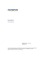
FVS-1000 MMP1
B
GND
A
700 mV
or more
B
G
R
Counter
clockwise
Set by selecting SD OUT
3
3
3
3
3
.
Mode No.
Setting
*
42
0000 7FFF 4A00 0A00
*
42.
40
80
60
40
*
43
ALL 0
*
44
ALL 0
*
46
FF
*
47
0400 7FFF 4A00 0A00
*
47.
0020 0100 0080 0040
*
60
ALL 0
*
61
ALL 0
3.
Turn ON the lamp power supply switch of the film
mounting unit. The lamp will light up.
Adjustment
1.
Connect the waveform monitor to D-1 SDI 1 of the
connector panel SD OUT board.
Set the waveform monitor mode to 3H, so that the
RGB waveforms can be observed on the same screen.
If the waveform on the waveform monitor is not
straight, it means that the camera moving table
assembly has been pulled out excessively. Return it
back slightly.
2.
Rotate the R, G, and B adjustment RVs fully in the
clockwise direction.
3.
Rotate the R, G, and B adjustment RVs slightly in the
counterclockwise direction, and stop just before the
waveform not clips.
Adjustment RV
Name
RV300/VA-158A
R-Ch VA OUT Level
RV500/VA-158A
G-Ch VA OUT Level
RV700/VA-158A
B-Ch VA OUT Level
Settings After Adjustments
1.
Turn OFF the lamp power supply switch of the film
mounting unit. The lamp goes off.
2.
Return the camera moving table assembly back to the
original position.
3.
Return the mode setting of the control panel back to
the original setting.
6-5-2. PR-239 Board Adjustment
Measuring instrument: Oscilloscope
Preparations
Set the menu of the control panel, and turn ON the INT SG
of the imager.
Menu setting: MENU
→
COLOR
→
TEST
→
SG ON
n
There is no need to draw out the board.
Adjustment
1. Offset adjustment
Connect the oscilloscope to the following CNs, and adjust
so that the waveform satisfies the specification.
Measuring Point
Adjustment RV
Name
CN101/PR-239 (E-5)
RV102/PR-239 (E-5)
R-ch OFFSET
CN201/PR-239 (G-5)
RV202/PR-239 (G-5) G-ch OFFSET
CN301/PR-239 (H-5)
RV302/PR-239 (H-5)
B-ch OFFSET
Specification:
A = 350
±
10 mV dc
Check that B is 70 mV or less.
6-5. Imager Adjustments
PR-239 board (A side)
1
2
3
4
5
RV102
CN101
CN201
CN301
RV202
RV302
A
B
C
D
E
F
G
H
Содержание BKFV-100/1
Страница 4: ......
Страница 10: ......
Страница 68: ......
Страница 72: ...2 4 FVS 1000 MMP1 1 1 1 1 1 7 6 8 9 1 1 5 4 2 3 Rear side 2 3 Location of Main Parts FVS T1000 Rear panel ...
Страница 78: ...2 10 FVS 1000 MMP1 4 5 6 8 8 9 7 3 2 1 Front side 2 3 4 Location of Sensors 2 3 Location of Main Parts ...
Страница 130: ......
Страница 194: ......
Страница 202: ......
Страница 248: ...7 4 FVS 1000 MMP1 O A 8321 649 E FILTER ASSY BOX S 1 758 295 11 IR UV CUT FILTER S 1 517 872 11 LAMP WITH PLASTIC CASE ...
Страница 250: ......
Страница 256: ......
Страница 258: ...Printed in Japan Sony Corporation 2001 12 08 B P Company 1999 FVS T1000 UC FVS P1000 SY E 3 202 167 04 ...